 |
www.riscos.com Technical Support:
RISC OS 3 User Guide |
| |


RISC OS 3.7 User Guide
A NAME="HEADING5_0">
17 - Draw
Draw is a powerful and sophisticated drawing package; you can use it to draw and edit diagrams and pictures made up from various kinds of graphical objects.
You will probably find that the easiest way of learning Draw is to read through the Basic ideas section which follows and then work through the Draw tutorial, before reading the more detailed sections.
Starting Draw
 |
Draw is in the Apps icon bar directory. To start Draw Double-click on the !Draw icon and it will install on the icon bar. Click on the Draw icon bar icon to open a new Draw window. |
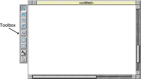
Alternatively, edit an existing drawing by dragging its file icon to the Draw icon on the icon bar, or by double-clicking on it.
Basic ideas
The Draw window
The Draw window looks similar to other application windows when you first load it, except that down its lefthand side there is a strip of icons called theToolbox (see picture above). The Toolbox allows you to draw or select objects without having to use menus.
Draw objects
A Draw diagram is built up from objects of a number of different types. Draw stores information about each object, which means you can subsequently change individual objects without affecting the other objects.
The basic object types are:
- Paths, consisting of a sequence ofline segments. Each line segment can be straight orcurved. A path can be closed to form apolygon or curved object, or leftopen. The path is the basic element of a drawing.
- Rectangles and ellipses, which are also path objects. This means that you can edit them.
- Text lines, in a range of fonts and sizes.
- Text areas, consisting of several lines of text. Text areas can be used for simple desktop publishing, and for annotating drawings.
- Sprites, which are graphic shapes made up of an array of coloured pixels. You can create sprites using Paint (see next chapter) and then load them into Draw.
- JPEG files (compressed photographic images) such as those in the
Images directory.
You can combine objects together as a group which you can then (usually) manipulate like any other object. Draw records the objects that were used to build a group, so that it may subsequently be 'ungrouped' into its constituents. Groups can also be used as components of other groups.
Each object has a style consisting of a number of attributes. Attributes are used to define the colours of an object, line widths, text fonts and sizes, and so on. The exact range of attributes depends on the type of object.
Draw modes
You can use Draw in three operating modes:
- Enter mode - used to create new Draw objects (like lines and squares).
- Select mode - used to change object attributes (like line colour) and to move and alter objects.
- Path edit mode - used to reshape an object by altering its paths and segments.
Don't worry about these names too much - when you're actually using Draw you'll change between the modes without thinking about it!
The mouse pointer changes according to which mode you are using: in Enter mode it is shown as a star, and in Select and Path edit mode as an arrow.
Tools and short-cuts
To make it easier to construct a diagram, Draw has a number of tools and shortcuts:
- The Toolbox is attached to the lefthand edge of each Draw window. You can use this to draw and edit shapes, without having to use menus.
- You can display a Grid to help you align objects in a diagram. Various different sizes and shapes of grid are available.
- Keyboard short-cuts duplicate the effect of the more frequent Draw actions. These are listed at the end of this chapter and also appear alongside the corresponding menu entries on the screen.
- You can use New view to display more than one view of a diagram; different views can have different grid and zoom factor settings. Changes made to the drawing in one view affect the other view as well.
The drawing area
When you start a drawing, the Draw window displayed on your screen only shows part of your actual drawing area. The drawing area is usually the size of an A4 sheet of paper, but you can make it as small as A5 or as large as A0, depending on the size of the drawing you want to create. You can also decide whether the drawing area is a landscape rectangle (where the horizontal side is longer) or aportrait rectangle (where the vertical side is longer). You can use the scroll bars on the Draw window to move around the drawing area.
Draw reference section
In this section, each of the Draw functions, including those you used in the tutorial, are explained in depth. Don't worry if you don't understand every last word; the real way to learn Draw is by using it.
Undoing and redoing operations
As you create a drawing, you will often decide that you want to undo the last operation you performed. It's easy to retrace your steps and correct any errors you make.
To::
- Undo the last change you made to your drawing: Choose Misc/Undo. You can also press F8; this is the keyboard short-cut you'll probably find most useful.
- Redo an operation, if you decide that you didn't need to undo it after all: Choose Misc/Redo. Keyboard short-cut: F9. You can Undo and Redo all the steps you performed since you last saved the file (providing the Undo buffer is sufficiently large - see the section Draw configuration.
Using the Grid to place objects accurately
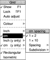 |
You can superimpose a rectangular or isometric grid on a drawing. This is useful for lining up objects and for checking their relative sizes. The grid is made up of 'major points' (marked by crosses)and 'minor points' (marked by dots).
You can use the grid either just as a general guide for drawing, or you can lock objects to it, so that they always align with points in the grid (the exception is if you rotate an object). When you are creating objects with grid lock turned on, you will see them attach to the nearest grid point to the pointer position. |
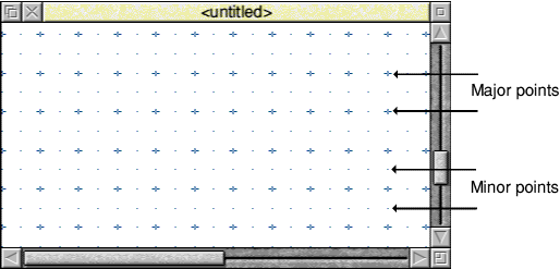
To:
- Switch the grid display on or off: Choose Grid/Show.
- Switch the grid lock on or off: Choose Grid/Lock. Causes new objects to align with the grid as you create them. Show need not be on in order to use Lock.
- Allow the grid spacing to change automatically: Choose Grid/Auto adjust. Draw inserts or removes minor points as you zoom in and out. Objects only lock to displayed points. Note: If you turn Auto adjust off and specify a very close spacing, the grid may take some time to draw.
- Change the colour of the grid points: Choose from the Grid/Colour submenu.
- Define the grid spacing: Choose a spacing from the Grid/Inch or Grid/cm submenu.
First number gives major point spacing. Second number gives number of subdivisions. You can define your own values at the bottom of the submenu. Just clicking on Inch or cm uses existing submenu settings. (See menu above)
- Set Y grid spacings to be different from X spacings: Enter the Y spacings in the Grid/Inch (y only) or Grid/cm (y only) submenu. X spacings are still taken from the Inch or cm submenus.
- Use a rectangular grid pattern: Choose Grid/Rectangular.
- Use an isometric grid pattern: Choose Grid/Isometric.
- Make existing objects snap to the grid: Choose Select/Snap to grid. The baseline of the text snaps to the grid. For grouped objects, the top left of the bounding box snaps to the grid.
- Snap all an object's control points to the grid: Go into Path edit mode and choose Edit/Snap to grid. Path edit mode is described in the section Editing Draw objects.
Zooming in and out of your drawing
 |
You can alter the apparent size of your drawing. For example, you might want to look at something close-up to position it accurately, or you might 'zoom out' to see your whole drawing at once. This doesn't alter the actual size of your draw objects. |
To:
- Zoom in and see your drawing at a higher magnification: Increase the ratio in the Zoom/Magnifier box, e.g. from 1:1 to 2:1, or from 1:2 to 1:1. Note that you can't have a number greater than
8 in the Magnifier box. You can also press Ctrl-W to zoom in by one magnification factor.
- Zoom out to see more of your drawing: Decrease the ratio in the Zoom/Magnifier box, e.g. from 2:1 to 1:1, or from 1:1 to 1:2. You can also press Ctrl-Q to zoom out by one magnification factor, or Shift-double-click Adjust.
- Zoom in on a particular area of your drawing: Shift-Adjust-drag a box around the area.
- Return to the previous zoom factor: Press Ctrl-R.
- Go back to original size (1:1): Press Ctrl-D.
- Lock the zoom factor: Choose Misc/Zoom lock.
Keyboard short-cuts are locked to 1:1, 1:2, 1:4, or 1>:8. For example, each time you press Ctrl-Q, you halve the zoom factor. When you press Ctrl-W, it's doubled.
If you scale up an object in !Draw and then highly magnify the view, the object may disappear. To retrieve the object, undo these operations. Reduce the object's scaling so that it doesn't disappear again.
Displaying two views of the same file
Choose Misc/New view to create a new view of the drawing you are editing, in a separate window. Edits you make in one view of a drawing show up in the other views as well. You can change the zoom on each view independently, use different grids in the separate views, scroll each one independently, and so on. To get rid of a view, close the window containing it.
Creating objects (Enter mode)
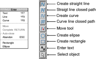 |
This section describes each tool in the Toolbox. These can also be selected from the Enter menu.
When you are in the process of creating any object (except text) you'll see a 'skeleton' version of it on the screen. |
Hints
You can cancel most operations part-way through by pressing Esc or choosing Enter/Abandon.
You can retrace your steps using Misc/Undo or the keyboard short-cut F8.
You can choose tools from the Toolbox on the lefthand side of the Draw window, or by using the Enter submenu.
To:
- Draw an open-ended path made up ofstraight and/orcurvedline segments: Choose the appropriate line tool. Click to place end points for each segment. Double-click to complete the path (or press Return, unless there are only two points). You can change tools part-way through constructing a path. You can also choose Enter/Line or Enter/Curve.
- Draw a closed path made up of straight and/or curved line segments: Choose the appropriate Joined line tool. Click to place end points for each segment. Double-click (or press Return) to complete the path. You can change tools part-way through constructing a path.
You can also switch Enter/Auto-close on and use Enter/Line or Enter/Curve.
If Auto-close is off, choose Enter/Complete or press Return to close the path.
- Create a multi-path object: Use the Move tool. See the section Creating a multi-path object for more information. You can also use Enter/Move.
- Draw an ellipse or circle: Choose the Ellipse tool. Click once to define the centre. Move pointer and click again to draw the ellipse. You can also choose Enter/Ellipse.
Turn Grid/Lock on to help draw a circle.
- Draw a rectangle or square: Choose the Rectangle tool. Click once to define a corner. Click again on the opposite corner. You can also choose Enter/Rectangle.
Turn Grid/Lock on to help draw a square.
- Enter a line of text: Choose the Text tool. Click where you want the line to start then type in your text. You can also choose Enter/Text.
If you are using anti-aliased fonts you may need to increase the size of thefont cache.
- Select an object so you can edit it: Choose the Select tool and click on the object. See the section on Editing Draw objects for more information
- Switch the Toolbox on and off: Press Menu and choose Toolbox. You can use the menu options described above to choose and use Draw's tools without using the Toolbox. You can also use keyboard short-cuts.
Drawing multi-path objects with the Move tool
Creating a multi-path object
To create one object made up from multiple paths:
- Choose one of the four line segment tools.
- Construct the first path by clicking on the end points of each segment (don't double-click at the end of the path).
- Click on the Move tool - the move icon will not be highlighted.
This lets you move to the start of another segment without drawing a line.
- Construct the next path.
- Repeat steps 1 to 4 until you've created all the paths and double-click to finish.
You will now have a single object, made up of many paths. You can't 'ungroup' such an object. You can edit it, though (see Editing Deaw objects).
Creating a hole in a filled object
Here's an example of how to create a filled rectangle with a transparent hole in it.
- Choose a fill colour from the Style/Fill colour dialogue box.
- Choose Style/Winding rule/Even-odd (don't worry about this for now - it's explained later).
- Draw a rectangle using the Straight line tool. Don't double-click to complete the shape, just click once to place the last point on top of the first).
- Click on the Move tool (the move icon will not be highlighted).
- Draw a smaller rectangle inside the first. When you double-click to complete the second rectangle you'll be able to see through the hole
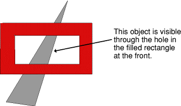
Note: You can't start or end a path with a Move.
This section tells you how to select and deselect objects, and how to manipulate a selection.
Selecting and deselecting objects
Choose the Select tool at the bottom of the Toolbox to enter Select mode. In Select mode, you can make changes to existing objects. To return to Enter mode and draw another object, choose one of the other tools.
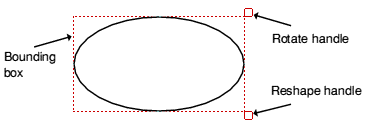
When you select an object you'll see its bounding box, with handles at two of its corners. Note that not all objects have these.
 To:
To:
- Select an object: Click on the object.
- Select a group of objects: Drag a select box around (or through) all the objects. You can also click Adjust on each object in turn.
- Select all objects in the drawing: Choose Select/Select all. You can also press Ctrl-A.
- Select only objects that lie wholly within a select box: Shift-drag a select box.: Normally, a select box selects everything it touches.
- Select an object obscured by another: Double-click over the object. If the object is one or more 'layers' deep, keep double-clicking to 'tunnel through' to it.
- Deselect an object: Click Adjust on the object.
- Deselect all currently-selected objects: Click Select on an empty part of the drawing. You can also choose Select/Clear or press Ctrl-Z.
Copying and deleting objects
To:
- Copy a selection: Choose Select/Copy. The new copy will be pasted into your drawing, slightly below and to the right of the original.
You can make multiple copies of an object by repeatedly pressing Ctrl-C.
- Delete a selection: Choose Select/Delete. You can also press Delete. If you want to retrieve a deleted object use Misc/Undo.
Moving objects to the front or back of a stack
To:
- Bring an object to the front of a stack : Choose Select/Front. Shortcut Ctrl-F
- Hide an object behind one or more other objects: Choose Select/Back. Shortcut Ctrl-B
Grouping and ungrouping objects
To:
- Group a selection: Choose Select/Group. Shortcut Ctrl-G
- Ungroup a selection: Choose Select/Ungroup. Shortcut Ctrl-U
Aligning objects (justification)
You can align objects, both vertically and horizontally.
To:
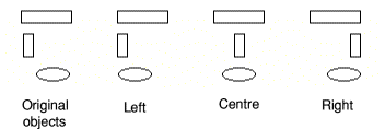
- Align a selection horizontally: Group the objects, then choose Left, Centre or Right from the Select/Justify menu.
- Align a selection vertically: Group the objects, then choose Top, Middle or Bottom from the Select/Justify menu.
Note: You need to group any objects before you can align them.
In the following example three objects have been grouped and then justified left, centre and right:
Moving, rotating and scaling objects
There are different ways of rotating and scaling objects, depending on how accurate you want the operation to be.
To:
- Move a selection: Drag it to the new position and release Select. If you move a selection when Grid/Lock is on, it moves in jumps of the grid spacing.
- Rotate a selection: Drag the Rotate handle at the top righthand corner of a bounding box. The selection rotates about its centre.
Note that you can't rotate Text in System font, Text areas or imported JPEG files (they have no Rotate handle).
- Rotate a selection by a specified angle: Enter the angle into the Transform/Rotate/Angle box.
- Resize a selection: Drag the Resize handle at the bottom right hand corner of a bounding box. Line widths are not scaled when you use this method. To preserve the aspect ratio of the object, use the method below.
- Resize (scale) an object accurately: Enter the scale factor into the Transform/Magnify box.
You can also choose to scale an object in the horizontal or vertical plane only. Choose Transform/Scale X for horizontal or Scale Y for vertical.
- Scale the line width of an object: Enter the scale factor into the Transform/Line scale box.
When you scale an object using this method its linewidth is scaled. You can also define the linewidth of an object along with its other style attributes. Note that you can't scale lines of width Thin.
Creating special effects in Draw (interpolation and grading)
Using interpolation and grading you can perform the following operations on two grouped objects:
- Change one object into the other object by inserting similar objects between them - cartoon animators call this 'in-betweening', 'tweening' or 'morphing'
- Create intricate patterns using the two objects.
Changing one object into another object (morphing or tweening)
To change one object into a different object:
- Draw two objects using the Joined line tool (see the sectionsRestrictions below.

- Group the two objects together.
- Enter the number of gradations into the Select/Interpolate or Select/Grade box (8 is the default value) and press Return.
A new set of objects will be drawn. Each new object is a partial transformation between the first object and the second object:


Interpolation produces a number of new paths, each consisting of two objects. You cannot ungroup these paths. This means that when you interpolate two objects you'll lose the original objects. It's best to (Copy them elsewhere in the Draw window before you interpolate them, or you can use Undo to start again.
Grading produces new objects which are not grouped as paths:
Creating intricate patterns
You can create interesting patterns if one object is inside (or on top of) the other.
You can interpolate between curved shapes to produce very intricate patterns:
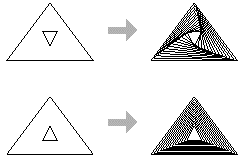
The difference between interpolation and grading is most evident when both shapes are closed and filled:
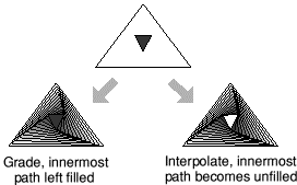
Properties used by interpolation and grading
The properties used by interpolation and grading are
- line colour
- fill colour
- line width
- triangle start/end cap height
- triangle start/end cap width.
Restrictions
A pair of path objects for interpolation or grading must have certain properties in common. For most practical purposes, this means they should be more or less the same shape (though they need not be the same size): two V-shapes, two rectangles, and so on. Specifically, the requirements are that;
- for each line or curve in one there must be a line or curve in the other
- for each move in one, there must be a move in the other
- for each close in one, there must be a close in the other
- objects must be drawn starting at the same end point
- objects must be drawn in the same direction (clockwise or anticlockwise)
- objects must be single-paths; they cannot be grouped objects.
Defining a path object's style

|
Each object has a style consisting of a set of attributes (such as fill colour, line colour, line width and so on). Using the various Style menu options, you can set the style to be applied to every new object you create in Enter mode
Any new object you create is given the style attributes currently defined in the Style menu. We suggest that you set up the style attributes before you actually draw an object. This can save you accidentally 'losing' objects because they're the same colour as the background. |
You can also alter the style of existing objects when in Select mode.
Here's how to define an object's style:
To:
- Define the width of line used to draw an object: Choose a width (in points) from the Style/Line width submenu, or define your own at the bottom of the submenu. 'Thin' means 'the narrowest width possible'. This produces different widths on different output devices. It's more sensible to use 0.25pt, especially if you'll be printing on a typesetter.
- Create path objects with coloured outlines : Choose a colour from the Style/Line colour window. There's lots of help on using the colour picker window in Using colour in applications.
- Fill path objects with a given colour: Choose a colour from the Style/Fill colour window. You can fill open objects as well as closed ones.
Complex objects will be filled according to which winding rule you've set - see the section Filling objects with colour - the winding rule.
- Make a path object transparent: Choose None from the Style/Fill colour window.
- Draw a dashed or dotted path object: Choose from the Style/Line pattern submenu.

You can modify dashed and dotted lines using the Start cap andEnd cap options; the cap settings apply to each segment in the line.
- Define how lines are joined together: Choose a join type from the Style/Join submenu.

This is only effective for thick lines.
- Define how lines start and end: Choose an end type from the Style/Start cap and End cap submenus.
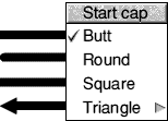
This only applies to open paths; it's only significant for thick lines. You can't add caps of any sort to Thin lines. You can use Start caps on a closed path with a dashed line style.
- Addarrows to line ends. This is an extension of the Start and End cap submenus. See the following section.
Adding arrows to line ends
Triangle caps are useful for creating arrows on the ends of line segments. You can set the height and width of a triangle cap independently. They are defined as multiples of the line width, as follows:
- Triangle height = Cap height x Line width
- >Triangle width = 2 x Cap width x Line width
Filling objects with colour - the winding rule
Style/Winding rule allows you to specify which of two methods is used to fill different regions of an object with colour. It only affects objects for which a fill colour has been set. It's not commonly used, but you'll need to understand it if you're creating objects with transparent holes.
An object can be a single path (e.g. an ellipse), a collection of line segments, or a single line segment that crosses over itself any number of times.
Non-zero winding rule
This rule fills regions on the basis of whether they were drawn in a clockwise or anti-clockwise direction.
Note each region's direction as you draw it, clockwise or anti-clockwise, and give it the direction a number +1 for one direction and -1 for the other.
To see if a region is to be filled, construct an imaginary line from inside the region to outside the object. Keep a total of the direction values for each line it crosses. If the total is non-zero the region will be filled (see the diagram below).
In the following example, three rectangles were drawn clockwise and one rectangle was drawn anti-clockwise. The clockwise rectangles were assigned a value of +1, and the anti-clockwise rectangles were assigned a value of -1.
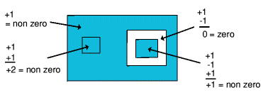
Even-odd winding rule
This rule fills regions if they are enclosed by an even number of other regions.
To determine whether a region inside an object is to be filled imagine a line passing from inside the region to outside the object. Count the number of lines it crosses. If the number is odd, the area will be filled.
The following example shows this rule applied to a single path object made up of four regions created using the Move tool. The image on the left shows the four rectangles before a fill colour was applied.

Defining text style
 |
You can change the style attributes of text lines using the Style menu. If you select a text line first, that line will have the style applied to it. All subsequent text lines will also have that style applied to them. |
To:
- Set the font name: Choose from the Style/Font name/Font list submenu. See the chapter Using fonts in applications for more details about using fonts.
- Set the font size: Choose from the Style/Font size/Size submenu. You can enter a different font size (in points) at the bottom of the submenu.
- Change the font height, but not its width: Choose from the Style/Font height/Size submenu.
- Define the colour of the text: Specify a colour using the Style/Text colour window.
- Set the colours used to anti alias fonts on a coloured background: Specify a colour using the Style/Background window. See below for more details on this.
Superimposing text on a coloured background
Style/Background sets the intermediate colours used around the edges of anti-aliased fonts. You don't usually need to worry about this, but it's useful if you're creating text on top of a coloured object
-
- Set the Text colour of your text line.
- Select the object on which your text is superimposed and note down its colour from the Style/Fill colour window.
- Set the Style/Background colour of the text line to be the same as that you noted down in step 2.
The anti-aliasing pixels will be in a range of shades between the Text colour and the Background colour. Background applies to text objects and text areas.
Note: This effect won't be visible if the text size is larger than the value set for anti-aliasing in Configure.
Editing Draw objects (Path edit mode)
All objects you construct using Draw's tools are made up of paths. In turn, paths consist of straight and curved line segments. Each segment in a path has end points and (if it is a curve) control points.
You change an object in two ways. You can resize it or transform it in Select mode, or you can change its basic shape (edit it) by going into Path edit mode and moving individual end points and control points.
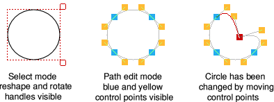
Note: You cannnot edit Text areas, JPEGs or sprites in Draw.
Entering and leaving Path edit mode
You can only edit a single-path object in Path edit mode so you will need to ungroup any objects first.
- Go into Path edit mode from Enter mode: Choose any path tool and click Adjust on the object you want to edit.
- Go into Path edit mode from Select mode: Select an object then choose Select/Edit. You can also press Ctrl-E once the object is selected.
- Edit an object (move a control point or end point): Drag the point with Adjust. There's more on editing below.
- Leave Path edit mode: Click Select on a blank area of the drawing.
Editing curves
Curved segments in a path object are defined by two end points and two control points. When drawing or editing a path, the control points are shown connected to the end points by straight lines.
The shape of a curve is determined by the control points as follows:
- The direction of the curve at the end point lies along the line connecting the end point to the control point (i.e. this line is a tangent to the curve).
- The degree to which the curve moves away from this straight line depends on the distance of the control point from the end point: the nearer together they are, the sooner the curve turns away.
By moving the control points, you can produce many different shapes of curve. Some examples are shown below. In each case the thick line shows the path itself, and the control points are joined to the corresponding end points by thin lines.
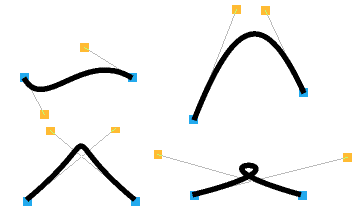
If you hold down Shift while you drag a control point, the corresponding control point in the next curve is also moved to keep the angle of join constant.
Editing text lines
When typing in text, you can only delete text and type new text in if you are still on the same line. As soon as you press Return or click somewhere else in the drawing, the line is 'frozen'.
To:
- Edit a 'frozen' text line: Select the text line and choose Select/Edit to display the Text box.

Then edit the text and click on OK. You can also press Ctrl-E after selecting the object.
- Convert each letter in a text line into an editable path object: Select the text line and choose Select/Convert to path. All the letters are grouped initially; to edit them individually, Ungroup them.
Note: Once you've converted text to a path you can't convert it back to a text line, nor can you convert text in System font.
Editing text as a path object
Once you've converted a text line to a path it can be treated like any other path object (for example, you can use Style options that apply to objects other than text.
For example, the following text was converted into a path, then ungrouped into individual letters, and each letter given a black line colour and a different fill colour (the second row of text was also given a much thicker line width).

Note: You can only convert outline fonts to a path.
Editing objects using the Path edit submenu
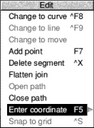 |
You can also change a path object's shape using menu options. This method gives you much greater control.
Enter Path edit mode. If the path you want to edit is under another object's path, double-click Adjust to tunnel through to the next deeper path. Select a segment by clicking Adjust on an end point or a control point. The line segment and end point will be highlighted (if you select the first end point of the path, there is no highlighting). Click Menu to show the Edit menu and now you can edit the highlighted segment and end point. |
To:
- Change a straight line segment into a curve: Choose Edit/Change to curve. Works if the selected segment is a line, or if you've selected a point inserted using a Move.
- Change a curved segment into a straight line: Choose Edit/>Change to line. Works on a curved line segment or a Move.
- Break a path at the highlighted segment (by replacing the segment with a Move operation): Choose Edit/Change to move. You can't change a segment to a move if it's at an end of the path, or if it's already preceded or followed by a move.
- Insert an extra point into the highlighted segment: Choose Edit/Add point. In effect, this adds an extra segment to the object, of the same type as the selected segment.
- Delete the highlighted segment: Choose Edit/Delete segment.
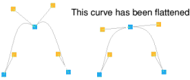
- Straighten the join between two segments: Choose Edit/Flatten join. This joins the control points by a straight line.
- Change a closed path into an open path, or vice versa: Choose Edit/Open path or Edit/Close path. This 'disconnects' or joins the first and last points in the path.
- Specify an end point's position accurately: Choose Edit/Enter coordinate and type the position into the New coordinates box.
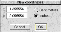
X and Y are offsets from the bottom lefthand corner of the drawing. You can specify them in inches or centimetres.
- Make all the end points in an object snap to their nearest major grid points: Choose Edit/Snap to grid.
How 'Flatten join' works
This flattens the join between two adjacent segments (unless both segments are straight lines). The curve is adjusted so that the tangent is continuous at the selected end point. For example:
How 'Change to move' works
If the path containing the line was closed, extra lines will be inserted to close each of the two sections of the path.

From left to right:
- Draw a boxed diamond shape in the order A, B, C, D.
- Click Adjust at 'C' to select segment B-C
- Choose Change to move which will replace B-C by a move. This will remove the line B-C and join C to A
The final picture shows the actual resulting shape.
Importing (loading) files into Draw
You can import five types of file into Draw.
- Existing Draw files and other files that use Draw's own file format
- Sprite files
- Text files, used to create text area objects (see later).
- Photo-quality images (JPEG files, see later).
- DXF files (see later).
To load any of the above file types into Draw drag the file's icon over the an open Draw window. When you do this the default settings of the dragged file are used.
To load any of the above file types into a new Draw window drag the file's icon over the Draw icon on the icon bar.
When you drag a file into a Draw window it is added to any objects already in the window. The file is loaded so that its bottom left hand corner lies at the mouse position at the instant the mouse button is released.
When you load a file by dragging it to the icon bar the file appears in a new Draw window, aligned to the bottom lefthand corner of the diagram.
Loading a sprite into Draw
 |
If you drag a sprite file containing many sprites into Draw only the first sprite
will be loaded. |
To avoid this problem with a multi-sprite file first load the sprite file into Paint. Now open a sprite window for the sprite you want to load into Draw. Make sure the sprite has a palette (click Menu and switch Edit/Palette on). Finally drag the icon in the Save/Sprite/Save as box into a Draw window.
This method also ensures that Draw displays the sprite in the correct colours.
Exporting (saving) files from Draw
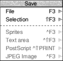 |
You can save objects from a Draw file in their own native file format. This means, for example, that if a Draw file has an imported sprite you can save that out as a sprite again.
Note: You need to be in Select mode to save anything other than the whole Draw file. |
To:
- Save the whole file as a Draw file: Use the Save/File/Save as box as normal.
- Save a selection of Draw objects as a Draw file: Use the Save/Selection/Save as box.
- Save the currently-selected sprite: Use the Save/Sprite/Save as box. You can only save a single sprite at a time, not a group or selection.
- Save a selected text area object: Use the Save/Text area/Save as box.
- Save the whole drawing as Encapsulated PostScript: Use the Save/PostScript/Save as box. You can use this to import the drawing into another application that accepts Encapsulated PostScript.
You must load !Printers and a PS printer definition file for this option to be available. You should not use Encapsulated PostScript files for printing as they do not contain page size information.
- Save a selected image as a JPEG file: Use the Save/JPEG Image/Save as box.
Note: The DrawFile format includes a 'Type 11' object which records details about the page size and orientation of the file. Some old applications may fail to load Draw files containing this object. To overcome this problem, load the Draw file into Draw, choose Select all and save the selection. This saves a Draw file without a type 11 object.
Printing Draw files
To print a Draw file:
- Make sure you have a printer connected and set up.
- Make sure that your drawing will fit on the paper on which you are going to print. Make sure that your drawing will fit on the paper on which you are going to print. Check Misc/Paper limits/Show then set the page size and orientation to match that of your printer.
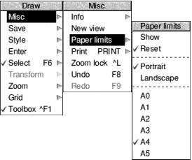
- Choose Misc/Print. Set the number of copies in the dialogue box and click on Print.

- Alternatively you can open the Print dialogue box by pressing the Print key.
Only objects within the inner limits of the grey border in the Draw file will be printed. The outer limits of the grey border correspond to the limits of the page. If no printer driver is loaded, the limits default to A4.
Misc/Paper limits/Reset sets the paper limits to the printer driver defaults.
Printing part of a diagram
You can also select part of the diagram to be printed at a time. This enables you to print a drawing on more than one sheet so that you can make up a poster, for example, from several standard-size sheets 'tiled' together.
- Choose Paper limits/Show.
- Hold down Ctrl and use one of these methods to define the printed area:
- click to mark the bottom lefthand corner of the printed area
- click Adjust to mark the top righthand corner
- drag a bounding box around the area you want to print; it will be scaled to fill the page when it is printed.
- Choose Misc/Print, or press the Print key.
Text areas
A text area is a special sort of object that allows you to perform simple 'desktop publishing'. A text area consists of a piece of text divided into one or more rectangular regions called text columns. Draw breaks up the text into lines which are just wide enough to fit into the columns, splitting it (principally) at spaces.
You can create a text area by using Edit (for example) to prepare a file containing the text, annotated with special commands (described below). When you load the text file into Draw, the text is formatted into columns. The number of columns is given by an annotation. You can move the text columns and change their size in Select mode. As you do this, Draw will reformat the text between the columns.
Text areas only use anti-aliased fonts. You cannot create a text area in the system font. If you try to use the system font you will find that it is automatically converted into the Trinity font. See Default text area header later. If you want to create a text area in system font, use the outline font version of the system font: choose Style/Font name/System/Fixed.
Creating and editing text areas
 |
To create a text area from a text file, drag the file into a Draw window. The columns in the text area are initially set up to standard sizes. If you drag the text file over the top of a selected text area, the old text in the area is replaced with the contents of the new file. Use this method for altering the text in a text area. |
Text area selection works in two slightly different ways, depending on how many text columns there are in the text area.
Single text columns
When there is a single text column in the text area, selection works in the same way as any other object. You can move the text area, scale it, change its style, and so on, as described above.
Multiple text columns
When there is more than one text column selection is a two-stage process. When you first click (or click Adjust, in multiple object selection) over the text area, the entire area is selected. You can move the area, but it cannot be scaled. Double-click (or double-click Adjust) to select a column of the text area. You can move and scale individual columns. Their new position and size need not lie within the original text area.
When you change the size of a text column, the text is reformatted to fit the new size of the column.
To select more than one column of a text area, select the first as described above, and select further ones by first clicking Adjust and then double-clicking Select over the column.
You can't rotate text areas and text columns (they don't have rotate handles).
Some select mode actions cannot be applied to text columns. If there are any text columns selected when you perform the operation, they are deselected first. An example of this is object deletion. You can delete a text area as a whole, but not a text column from within it.
An example
Try typing the following text into Edit and loading it into Draw
as an Edit file:
    \! 1
    \AD
    \D2
    \F0 Trinity.Medium 24
    \L24
    \P24
    This is an example of a text area containing two columns. The
    text was prepared in Edit, and then saved directly into Draw.
    The columns were then stretched to the right size, using select
    mode, and the rectangles added.
This creates the following text area.
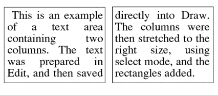
The appearance of a text area is determined from commands which are included in the text used to create it. Each command starts with a backslash (\) character. The full list of sequences is given below, but the following is a brief description of the commands used in the example.
- \! 1 tells Draw that this is a text area.
- \AD causes the text to be justified to left and right in its columns.
- \D2 indicates the number of columns to be displayed.
- \F0 Trinity.Medium 24 specifies font 0 as Trinity.Medium, 24pt.
- \L24 sets the line spacing to 24pt.
- \P24 sets the spacing between paragraphs to 24pt. In this example, this just affects the space after the title.
- \0 selects font 0 for the following text.
Text area commands
The following is a complete list of text area commands. Some commands must be terminated with either a newline or a slash (/) character. Others do not need a terminator (for example, where the command has a fixed number of characters) but may optionally end with a slash character. For clarity, it is often useful to include it. Note especially that all commands are case sensitive; this is unusual in RISC OS and applications written for it.
In the following descriptions
- Items in italics (for example code) indicate a parameter you must supply.
- Items in square brackets are optional (for example [/] indicates an optional slash character).
- Commands and parameters must normally be separated by spaces (though there does not have to be a space between the command and the first parameter).
- Return means a single newline character, and Return/ means newline or /.
Here is the full list of Commands and their effects:
- \! version Return/: This is a special line which must appear at the start of any file which is to be used for a text area. version must be 1. However, it forms part of a default header which is inserted at the start of the text; this is described below.
- \A code [/]: Set alignment. code may be L (left aligned), R (right aligned), C (centred) or D (double, i.e. justified to both margins). An alignment setting forces a line break. The default setting is left aligned.
- \B red green blue Return/: Set the background colour to the given red/green/blue intensity, or the best available approximation. Each intensity is in the range 0 to 255; values outside this range will be limited to it (i.e. a value set higher than 255 will be realised as 255; a value set to less than 0 will be realised as 0). Background colour is used in the same way as for text objects; you should set it to be the same as the area of the drawing that the text area is to appear in front of (the text area itself is effectively transparent). The default is the background style attribute of the text area object, normally white (equivalent to \B 255 255 255).
- \C red green blue Return/: Set the text colour to the given red/green/blue intensity, or the best available approximation. Each intensity is in the range 0 to 255; values outside this range will be limited to it. The default is the text colour style attribute of the text area object, normally black (equivalent to \C 0 0 0).
- \D columns Return/: Indicates that the text area is to contain the indicated number of columns. This must appear before any printing text. The default is 1.
- \F font-number name size [width] Return/: Defines a font reference. font-number is either one or two digits. The font number is used subsequently to set the font. name is a font name such as Trinity.Medium. size and width are the height and width of the font in points. If width is omitted, the size is used for both height and width. There are no defaults.
- \font-number [/]: Indicates that the text from the point at which the command appears is to appear in the specified font. If the font is not available when the text is being drawn, the effect is undefined. Draw will attempt to check that the font number and the corresponding definition are reasonable. There is no default.
- \L line-spacing Return/: Sets the line spacing (the distance from the base of the characters in one line to the base of the characters in the next) to the given value, measured in points. Line spacing changes take effect from the end of the output line in which the command appears. The default is 10pt.
- \M left-margin right-margin Return: Sets the left and right margins to the given values, measured in points. If the total size of the margins is greater than the width of the column, no text is displayed. Margin settings apply from the end of the output line in which the command appears. The default is 1pt at each side.
- \P paragraph-spacing Return: Sets the extra space inserted between paragraphs to the given value, measured in points. Paragraph spacing changes take effect from the end of the output paragraph in which they appear. The default is 10pt.
- \U position thickness Return: Switches on underlining, at the given position relative to the base of the characters. position is limited to the range -128 to 127, and thickness to the range 0 to 255. Both values are measured in units of 1/256 of the current font size. Underlining may be turned off by specifying a thickness of 0.
- \U. [/]: An alternative way of turning underlining off.
- \V[-] vertical-move [/]: Moves the following text by the given amount, measured in points, relative to the current character position. This is intended for superscripts and subscripts; use positive values for superscripts, negative values for subscripts.
- \-: Inserts a soft hyphen. This tells Draw that it may split the word at this point if necessary, inserting a hyphen character in the output. If the word is not split at the soft hyphen, it has no printing effect.
- \Return: Forces a line break.
- \\: Inserts a backslash character.
- \;text Return: Treated as a comment. Characters up to and including the next newline are ignored.
Rules for displaying text areas
Line splitting
Draw displays text in text areas by splitting it into lines and columns. When deciding where to split the text, Draw tries to split it at the space or soft hyphen that gives the most characters that will fit in the column. If this is not possible, the text is split at the character that gives the longest line that just fits in the column.
Special characters and paragraph formatting
Certain characters have special interpretations:
- All control characters are ignored, except tabs, which are treated as spaces.
- Newline characters appearing before any printing text insert a paragraph spacing.
- A single newline character in the body of the text is treated as a space, unless it is preceded or followed by a space, in which case it is ignored.
- A sequence of 'n' newline characters in the body of the text inserts 'n-1' paragraph spacings.
For columns other than the first, paragraph spacings at the head of the column are ignored. Lines which protrude vertically beyond the limits of the column are not displayed; however, all commands occurring in them are interpreted. This can occur if the line spacing is significantly smaller than the font height. You should take care (by using the \M command) to ensure that lines do not protrude beyond the limits of the column horizontally, since the text may not be displayed correctly in this case. The only circumstances in which this is likely to happen are when an italic font is used and the margin setting does not allow for it.
Font usage
When a text area is being constructed from a text file, or being loaded as part of a Draw file, checks are made on the fonts contained in it. If a font is not available, a warning message is displayed. Text that should be in this font will appear in the most recently-used font.
Exporting text from a text area
You can re-export text used to construct a text area back into a text file, by choosing Save/Text area. This can be useful for altering text areas in a Draw file, when the original text file used to create them is no longer available.
Default text area header
If the text does not start with a version number line (\! 1), Draw will insert the following standard header:
    \! 1
    \F 0 Trinity.Medium 12
    \F 1 Corpus.Medium 12
    \0
    \AD
    \L12
This defines two font references, sets the text to be displayed in font 0 (Trinity Medium) justified to both left and right margins, with a line spacing of 12pt. If you subsequently export the text, the standard header will be exported as well.
DXF files
Draw can read files in DXF (data interchange) format. This is a file format used by other graphics programs such as AutoSketch. Draw cannot save files in DXF format.
When you load a DXF file into Draw by dragging it into a window or onto the Draw icon, a dialogue box appears, in which you can specify:
- whether coordinates and sizes in the file are to be interpreted as being in inches or centimetres;
- a scaling unit to be applied to all coordinates and sizes;
- the name of the font in which text is to be plotted. If the name you give is blank, or is not the name of an outline font known to Draw, the text will be plotted in the system font.
To load the file, click on OK. If you click on Abandon, the file is not loaded.
The following restrictions apply to DXF files loaded into Draw:
- The following DXF object types are not implemented: SHAPE, ATTDEF, ATTRIB, 3DLINE, 3DFACE, DIMENSION.
- Line types are ignored: all lines are created as solid.
- Layers are not implemented.
- Text justification may be approximate in outline fonts.
- Straight line objects are drawn in a single width and colour.
- Colours are guessed from a set of standard values. Unknown colours are converted to black.
LI>Text may not be rotated or oblique. The text style table is not used. There is no backwards or upside-down plotting.
- A single font is used for all the text in the file.
- There is no curve fitting.
- Block INSERTs do not use column and row values, attribute entries, rotation, or z scaling.
JPEGs (photo-quality images)
Draw can read files in JPEG format. JPEG stands for Joint Photographic Experts Group, and is a standard format for compressing photographic images (see the pictures in the Images directory, for example).
Unlike Paint, if you load a JPEG into Draw, all the original file information is kept. This means, amongst other things, that you can save an imported image back out of Draw as a JPEG file again. It also means that if you change from one screen mode to another with more colours, you'll see an imported JPEG file at a higher quality.
When you display a DrawFile containing a JPEG object, the graphics system requires some workspace for processing the JPEG data. You can see this on your Tasks display as the dynamic area 'JPEG Workspace', and its required size depends on the width in pixels of your JPEG image.
If there is insufficient free memory to allocate this workspace, Draw displays a JPEG image as a light grey rectangle containing the message 'Not enough memory available to plot JPEG'.
Some third-party applications not updated to use the JPEG features of RISC OS 3 will correctly load a DrawFile containing a JPEG image, but display a blank box where the JPEG image should be. Other applications may fail to load such a DrawFile.
If this is a problem, use !Paint or !ChangeFSI to convert your JPEG images into sprites, and replace the JPEG images in your DrawFile with these sprites. This can produce a DrawFile of the same appearance, but using far more space on disc and in your computer's memory to store.
Working with multiple Draw files
You can work on several Draw files at the same time; simply click on the Draw icon on the icon bar to start up another Draw window.
It's easy to copy objects between Draw windows. Select the object you want to copy, move the pointer to the destination Draw window and choose Select/Copy. The selected object is copied into the new window. Alternatively you can use the Save and Save Selection menu options to drag Draw icons into new Draw windows.
If you are working with multiple Draw windows, only one window can be 'active' at a time. So, if you select an object in one window and then select an object in another window, you will nullify the selection in the first window. Additionally clicking on the Draw icon to create another Draw window also nullifies any current selection.
Saving Draw features in a Desktop boot file
You may want to change some aspects of the way new Draw windows appear. For example, a new window normally opens with the Joined line tool selected, but you may prefer to have the Select tool ready to use each time you start Draw.
You can set features of this type by setting up Draw as you want to use it, then save these features by creating a Desktop boot file. Instructions on how to create a Desktop boot file are given in Desktop boot files.
There are several features of Draw that you can set before saving a Desktop boot file, so that they are set up the way you want them each time you switch on. The Draw features that will be recorded when you go through this process are known as Draw$Options (see the section Configuring applications).
Keystroke equivalents
Many Draw operations can be carried out from the keyboard instead of the menus and mouse; when you are familiar with the application, you may find this more convenient.
In Enter mode
Actions and their keystroke equivalents:
- Save a file (calls up the normal Save as dialogue box): F3
- Save a selection: Shift-F3
- Save a sprite or JPEG Image: Ctrl-F3
- Save a text area: Shift-Ctrl-F3
- Load a named file (calls up a dialogue box into which you can type the name of the file you want to load): F2
- Insert a named file (calls up a dialogue box into which you can type the name of the file to insert into the Draw file you are working on): Shift-F2
- Close a window: Ctrl-F2
- Print a file: Print
- Toggle between show and hide grid: F1
- Toggle Lock to grid on and off: Shift-F1
- Switch the Toolbox on or off: Ctrl-F1
- Zoom out: Ctrl-Q
- Zoom in: Ctrl-W
- Zoom to 1:1: Ctrl-D
- Go back to the previous zoom: Ctrl-R
- Set the Zoom lock: Ctrl-L
- Undo an action: F8
- Redo an action: F9
- Enter Select mode: F6
- Move the pointer one pixel: Up, down, left and right cursor keys
In Select mode
Actions and their keystroke equivalents:
- Copy a selection: F7 or Ctrl-C
- Delete a selection: Shift-F8, Delete, or Ctrl-X
- Clear a selection: Shift-F6 or Ctrl-Z
- Select all: F5 or Ctrl-A
- Bring a selection to the front: Ctrl-F4 or Ctrl-F
- Send a selection to the back: Ctrl-Shift-F4 or Ctrl-B
- Group a selection: F4 or Ctrl-G
- Ungroup a selection: Shift-F4 or Ctrl-U
- Snap a selection to grid: Shift-F5 or Ctrl-S
- Enter Path edit mode: Ctrl-F6 or Ctrl-E
- Justify a selection: Ctrl-F5 or Ctrl-J
In Path edit mode
Actions and their keystroke equivalents:
- Change a line to a curve: Ctrl-F8
- Change a curve to a line: Ctrl-F9
- Add a point: F7 or Ctrl-C
- Delete a segment: Shift-F8, Delete or Ctrl-X
- Enter a coordinate: F5
- Finish a path edit: Return
- Snap to the grid: Shift-F5 or Ctrl-S
For tool selection
Actions and their keystroke equivalents:
- Enter text: Ctrl-F7 or Tab
- Enter a closed line: Ctrl-F9
- Enter a closed curve: Ctrl-F8
- Complete a path: Return
- Abandon an operation: Escape
RISC OS 3.7 User Guide - 22 JAN 1997


This edition Copyright © 3QD Developments Ltd 2015
Last Edit: Tue,03 Nov 2015


 To:
To:


