
|
www.riscos.com Technical Support: |
All ARM instructions are conditionally executed, which means that they will only be executed if the N, Z, C and V flags in the PSR are in the correct state at the end of the preceding instruction. The condition is encoded in a four bit condition field, held in bits 28 - 31 of an instruction. By default ObjAsm encodes the 'always execute' condition; other conditions can be requested by appending a two-character condition mnemonic to ObjAsm's mnemonic for an instruction.
The figure below shows the condition codes, their mnemonics, and the corresponding conditions under which the instruction is executed:
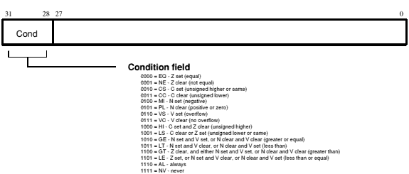
The condition field
Note that ObjAsm implements HS (Higher or Same) and LO (LOwer than) as synonymous with CS and CC respectively, giving it a total of 17 condition mnemonics.
For example, suppose you had a CMP (compare) instruction followed by an instruction with the EQ condition (so it is executed only if the Z flag is set):
Branches which are taken cause breaks in the pipeline. For this reason they often waste time, and can sometimes be replaced by a suitable conditional instruction sequence.
As an example, the coding of IF A=4 THEN B:=A ELSE C:=D+E might be conventionally achieved using five ARM instructions:
        CMP     R5,#4           ; test "A=4"
        BNE     LABEL           ; if not equal goto LABEL
        MOV     R6,R5           ; do "B:=A"
        B       LAB2            ; jump around the ELSE clause
LABEL   ADD     R0,R1,R2        ; do "C:=D+E"
LAB2                            ; finish
whereas, using the condition testing instructions, the same effect may be achieved using three instructions:
        CMP     5,#4            ; test "A=4"
        MOVEQ   R6,R5           ; if so do "B:=A"
        ADDNE   R0,R1,R2        ; else do "C:=D+E".
If the condition tested is true, the instruction is performed. If it is false, the instruction is skipped and the PC is advanced to the next memory word, which takes little processor time. The first of the examples above takes about twice as long as the second.
After the instruction is obeyed, the arithmetic logic unit (ALU) will output appropriate signals on the flag lines. On certain instructions, the flags set the condition code bits in the PSR; for other instructions, the flags in the PSR are only altered if the programmer permits them to be updated.
The arithmetic logic unit has a 32-bit barrel shifter capable of various shift and rotate operations. Data involved in the data processing group of instructions (detailed in the Data processing) may pass through the barrel shifter, either as a direct consequence of the programmer's actions, or as a result of the internal computations of ObjAsm. The barrel shifter also affects the index for the single data transfer instructions (detailed in the Single data transfer (LDR, STR)).
The barrel shifter has a carry in, which takes its input from the C flag of the PSR; and a carry out, which may be latched back into the C bit of the PSR for logical data operations (see The S bit).
The shift mechanism can produce the following types of operand:
Syntax: register
For example: RO
A register shifted by a constant amount, in the range 0-31, 1-31 or 1-32 (depending on shift type).
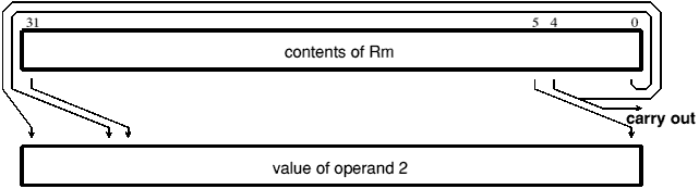
A value which is the result of rotating a register and the carry bit one bit right. Because the carry is included in the shift, 33 bits (rather than 32 bits) are affected. The shift type is known as rotate right extended.
A register shifted by n bits, where n is the least significant byte of a register. This form is not valid as an index in a single register transfer.
A constant constructed by rotating an 8-bit constant right by 2n bits, where n is a 4-bit constant. The shift type is always rotate right. This form is not valid as an index in a single register transfer.
Syntax: #expression
For example: #&3FC
Note that the rotation is invisible to the programmer, who should merely supply an immediate value for the data processing instruction to use.
ObjAsm will evaluate the expression and reject any number which cannot be expressed as a rotation by an even amount of a number in the range 0-255. If possible, ObjAsm always constructs it as an unrotated value, even if there are other possibilities.
Examples of valid immediate constants are:
#1
#&FF
#&3FC       This is &FF rotated right by 30
#&80000000  This is 2 rotated right by 2
#&FC000003  This is &FF rotated right by 6.
Examples of invalid constants are:
#&101       cannot be obtained by rotating an 8-bit value
#&1FE       an 8-bit value rotated by an odd amount - but not an
            8-bit value rotated by an even amount.
A constant constructed as in the point above, but specified explicitly. This form is not valid as an index in a single register transfer.
Syntax: #constant, rotate amount
For example: #4,2
The shift amount should be an even number in the range 0-30. This can be important for setting the carry flag on an operation which would otherwise not update it.
For example:
MOVS    R0, #4,2        produces the same result as
MOVS    R0, #1
but because the first instruction does a rotate right of two bits the carry flag is cleared, whereas it is not altered by the second instruction.
Various instructions use the barrel shifter to shift register operands. The effects of such shifts are detailed in this section, rather than being repeated for each instruction.
There are six assembler mnemonics for shift types, used to control the barrel shifter. These are:
| LSL | Logical Shift Left |
| ASL | Arithmetic Shift Left |
| LSR | Logical Shift Right |
| ASR | Arithmetic Shift Right |
| ROR | Rotate Right |
| RRX | Rotate Right with Extend |
The mnemonic ASL (arithmetic shift left) may be freely interchanged with LSL (logical shift left).
The shift amount may either be specified in the instruction, or in a register specified by the instruction.
When the shift amount is specified in the instruction, it is contained in a 5 bit field which may take any value from 0 to 31.
Only the least significant byte of the contents of Rs is used to determine the shift amount.
If this byte is zero, the unchanged contents of Rm will be used as the second operand, and the old value of the PSR C flag will be passed on as the shifter carry output.
If the byte has a value between 1 and 31, the shifted result will exactly match that of an instruction specified shift with the same value and shift operation.
If the value in the byte is 32 or more, the result will be a logical extension of the shifting process. This is detailed for each mnemonic described below.
| Rm,LSL #n or Rm,ASL #n | Shift contents of Rm left by n bits, where n is 0 to 31. |
| Rm,LSL Rs or Rm,ASL Rs | Shift contents of Rm left by the least significant byte of Rs. |
A logical shift left (LSL) takes the contents of Rm and moves each bit by the specified amount to a more significant position. The least significant bits of the result are filled with zeroes. The high bits of Rm which do not map into the result are discarded - except that the least significant discarded bit becomes the barrel shifter's carry out.
For example, the effect of LSL #5 is:
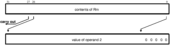
A logical or arithmetic shift left by 5
The barrel shifter's result is the unchanged contents of Rm, and its carry out is the old value of the PSR C flag.
The result is zero, and the carry out is bit 0 of Rm.
Both the result and the carry out are zero.
| Rm,LSR #n | Shift contents of Rm right by n bits, where n is 1 to 32. |
| Rm,LSR Rs | Shift contents of Rm right by the least significant byte of Rs. |
A logical shift right (LSR) is similar to a logical shift left, but the contents of Rm are moved to less significant positions in the result. LSR #5 has this effect:
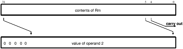
A logical shift right by 5
Logical shift right zero is redundant as it is the same as logical shift left zero. The form of the shift field which might be expected to correspond to LSR #0 is therefore used to encode LSR #32. ObjAsm assembles LSR #0 (and ASR #0 and ROR #0) as LSL #0, and allows you to specify LSR #32.
This is assembled as LSL #0 (see Logical shift left, or arithmetic shift left), which has the same effect as LSR #0.
The barrel shifter's result is the unchanged contents of Rm, and its carry out is the old value of the PSR C flag.
The result is zero, and the carry out is bit 31 of Rm. (LSR #32 is encoded in the format you would expect to correspond to LSR #0.)
Both the result and the carry out are zero.
| Rm,ASR #n | Shift contents of Rm right by n bits, where n is 1 to 32. |
| Rm,ASR Rs | Shift contents of Rm right by the least significant byte of Rs. |
An arithmetic shift right (ASR) is similar to a logical shift right, except that the high bits are filled with bit 31 of Rm instead of zeroes. This preserves the sign in 2's complement notation. For example, ASR #5:
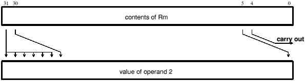
An arithmetic shift right by 5
Arithmetic shift right zero is redundant as it is the same as logical shift left zero. The form of the shift field which might be expected to correspond to ASR #0 is therefore used to encode ASR #32. ObjAsm assembles ASR #0 (and LSR #0 and ROR #0) as LSL #0, and allows you to specify ASR #32.
This is assembled as LSL #0 (see Logical shift left, or arithmetic shift left), which has the same effect as ASR #0.
The barrel shifter's result is the unchanged contents of Rm, and its carry out is the old value of the PSR C flag.
Each bit of the result is equal to bit 31 of Rm; the result is therefore all ones or all zeroes. The carry out is also bit 31 of Rm. (ASR #32 is encoded in the format you would expect to correspond to ASR #0.)
| Rm,ROR #n | Rotate contents of Rm right by n bits, where n is 1 to 31. |
| Rm,ROR Rs | Rotate contents of Rm right by the least significant byte of Rs. |
Rotate right (ROR) operations reuse the bits which 'overshoot' in a logical shift right operation by reintroducing them at the high end of the result, in place of the zeroes used to fill the high end in logical right operations. For example, ROR #5:
A rotate right by 5
Rotate right zero is redundant as it is the same as logical shift left zero. The form of the shift field which might be expected to correspond to ROR #0 is therefore used to encode rotate right extended (see the next section). ObjAsm assembles ROR #0 (and LSR #0 and ASR #0) as LSL #0.
This is assembled as LSL #0 (see Logical shift left, or arithmetic shift left), which has the same effect as ROR #0.
The barrel shifter's result is the unchanged contents of Rm, and its carry out is the old value of the PSR C flag.
The result is equal to Rm, and the carry out is bit 31 of Rm.
The result and carry out are the same as for ROR ((Rs - 1) MOD 32 + 1); therefore repeatedly subtract 32 from Rs until its value is in the range 1 to 32, and then see above.
| Rm,RRX | Rotate contents of Rm and the carry flag right by 1 bit only. |
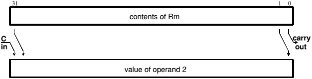
The form of the shift field which might be expected to give ROR #0 is used to encode a special function of the barrel shifter, rotate right extended (RRX). This is a rotate right by one bit position of the 33 bit quantity formed by appending the PSR C flag to the most significant end of the contents of Rm:
The ARM can work with up to 16 external coprocessors, which (if present) will execute the instructions listed below. If the requested coprocessor is absent, these instructions will be regarded as undefined. The undefined instruction trap can then take appropriate action (for example emulating the requested instruction in software or telling the user that the program won't run in a machine without the coprocessor.)
The floating point coprocessor uses coprocessor numbers 1 and 2. If it's absent, the floating point emulator traps the resulting undefined instructions and emulates them. The coprocessor 15 instructions are used by ARM as instructions to control its own operation (such as cache control, and 26/32 bit configuration).
ObjAsm provides support for coprocessors at two levels. Firstly, it provides a set of generic coprocessor instructions, detailed below. Secondly, it recognises a standard set of floating point instructions and translates them into the appropriate coprocessor instructions; see the chapter entitled Floating point instructions for details.
All the generic coprocessor operations include a coprocessor number symbol and one or more coprocessor register symbols. These should be defined using the CP and CN directives respectively. (See the chapter entitled Directives.)
All coprocessor instructions are conditional. Whether they are executed depends on the ARM's condition flags, not on any coprocessor status register.
Instructions for branching to an instruction other than the next one
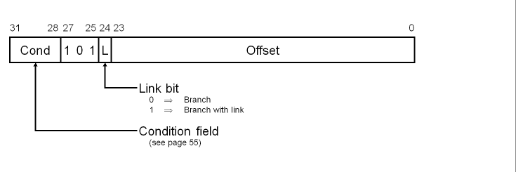
B«L»«cond» expression
where:
| «L» | requests the Branch with Link form of the instruction (see The link bit below). If absent, R14 will not be affected by the instruction. |
| «cond» | |
| expression | is a program-relative expression describing the branch destination, from which ObjAsm calculates the offset. |
These instructions branch to an instruction other than the next one, by altering the value of the program counter (R15). The Branch with Link form of the instruction also stores a return address in the link register (R14), so that program flow can branch to a subroutine, and then return to the instruction immediately following the Branch with Link instruction; for more details see The link bit below.
All branches take a signed 2's complement 24 bit word offset. This is shifted left two bits, and added to the program counter, with any overflow being ignored, giving an offset of ±32Mbytes. The branch can therefore reach any word aligned address within a 26 bit address space, since the calculation 'wraps round' between the top and bottom of memory.
When using this instruction with ObjAsm you should provide a label, from which ObjAsm will calculate the 24 bit offset.
The encoded offset must take account of the effects of pipelining and prefetching within the CPU, which causes the PC to be two words ahead of the current instruction. ObjAsm automatically handles this for you. For example, the calculated jump offset in the following piece of code is 000000, even though the jump is to a label two PC locations ahead.
| Code generated | Label | Mnemonic | Destination |
|---|---|---|---|
| EA000000 | L1 | BEQ | L2 |
| xxxxxxxx | xxx | ||
| xxxxxxxx | L2 | xxx |
The instruction is only executed if the condition specified in the condition field is true (see the chapter entitled The condition field).
Branch with Link works in the same way as Branch, but it also writes the old PC and PSR into the link register (R14) of the current bank. The PC value written is first adjusted to allow for the prefetch, and contains the address of the instruction following the branch and link instruction.
This form of the instruction is often used for branching to subroutines. At the end of the subroutine the program flow can return to the instruction immediately following the Branch with Link instruction by writing the link register (R14) value back into the program counter (R15). To do so, the subroutine should end with:
MOV PC,R14
if the link register has not been saved on a stack, or:
LDMxx Rn,{PC}
if the link register has been saved on a stack addressed by Rn. (xx is the stack type; see the chapter entitled Block data transfer (LDM, STM).)
These methods of returning do not restore the original PSR. If the PSR does need to be restored then
MOV PC,R14
can be replaced by
MOVS PC,R14
or
LDMxx Rn,{PC}
by
LDMxx Rn,{PC}^
However, care should be taken when using these methods in modes other than user mode, as they will also restore the mode and the interrupt bits. In particular, restoring the interrupt bits may interfere unintentionally with the interrupt system.
In 32 bit operation, the offset is sign extended to 32 bits before it is added to the program counter.
Branches beyond ±32Mbytes must use an offset or an absolute destination which has previously been loaded into a register. In this case you should manually save the PC in R14 if you require a Branch with Link type operation.
Branch with Link does not save the CPSR with the PC. If you need to preserve the CPSR over a subroutine, it is your responsibility to explicitly save and restore it, either on entry to and exit from (respectively) the subroutine, or in the calling part of the program.
here    BAL     here            ; Assembles to EAFFFFFE
                                ; (note effect of PC offset)

        B       there           ; ALways condition used as default

        CMP     R1,#0           ; Compare register 1 with zero
        BEQ     fred            ; Branch to fred if register 1 was zero,
                                ; otherwise continue to next instruction

        BL      sub + ROM       ; Unconditionally call subroutine at
                                ; computed address

        ADDS    R1,#1           ; Add 1 to register 1, setting PSR flags on
                                ; the result
        BLCC    sub             ; Call subroutine if the C flag is clear,
                                ; which will be the case unless R1 contained
                                ; FFFFFFFFH
                                ; Otherwise continue to next instruction
Instructions for performing arithmetic or logical operation on one or two operands
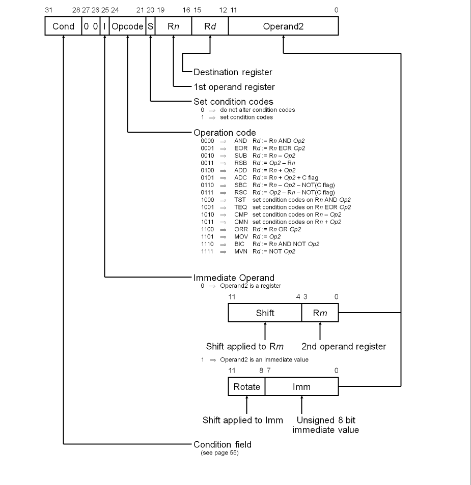
The data processing instructions use three different types of syntax, depending on whether the opcode being used takes one or two operands, and whether or not it writes the result into a destination register:
opcode«cond»«S»Rd,op2
opcode«cond»«P»Rn,op2
opcode«cond»«S»Rd,Rn,op2
| opcode | is a mnemonic for the data processing operation to be performed; see Opcodes below |
| «cond» | is a two-character condition mnemonic; see the chapter entitled The condition field. |
| «S» | means to set the PSR's condition codes from the operation. ObjAsm forces this for CMN, CMP, TEQ and TST, provided the P flag is not specified. See Opcodes below for a summary of the flags affected by each opcode, and The S bit for more detail. |
| «P» | means to take the result of a CMN, CMP, TEQ or TST operation, and move it to the bits of R15 that hold the PSR - even though the instruction has no destination register. Bits corresponding to the PC are masked out, as are (in User mode) the I, F, and mode bits. |
| Rd, Rn & Rm | are expressions evaluating to a valid ARM register number. |
| op2 | may be any of the operands that the barrel shifter can produce.
The syntax is Rm«,shift» or #expression If #expression is used, ObjAsm will attempt to match the expression by generating a shifted immediate 8-bit field. If this is impossible, it will give an error. shift is shiftname Rs or shiftname #expression, or RRX (rotate right one bit with extend). shiftnames are: ASL, LSL, LSR, ASR, and ROR. (ASL is a synonym for LSL, and the two assemble to the same code.) See Shift types. |
The opcodes supported are:
| Assembler Mnemonic | Meaning | Operation | Flags affected |
|---|---|---|---|
| ADC | Add with Carry | Rd:=Rn + op2 + C flag | N,Z,C,V |
| ADD | Add | Rd:=Rn + op2 | N,Z,C,V |
| AND | And | Rd:=Rn AND op2 | N,Z,C |
| BIC | Bit Clear | Rd:=Rn AND (NOT(op2)) | N,Z,C |
| CMN | Compare Negated | Rn + op2 | N,Z,C,V |
| CMP | Compare | Rn - op2 | N,Z,C,V |
| EOR | Exclusive Or | Rd:=Rn EOR op2 | N,Z,C |
| MOV | Move | Rd:=op2 | N,Z,C |
| MVN | Move Not | Rd:=NOT op2 | N,Z,C |
| ORR | Logical Or | Rd:=Rn OR op2 | N,Z,C |
| RSB | Reverse Subtract | Rd:=op2 - Rn | N,Z,C,V |
| RSC | Reverse Subtract with Carry | Rd:=op2 - Rn - NOT(C flag) | N,Z,C,V |
| SBC | Subtract with Carry | Rd:=Rn - op2 - NOT(C flag) | N,Z,C,V |
| SUB | Subtract | Rd:=Rn - op2 | N,Z,C,V |
| TEQ | Test Equivalence | Rn EOR op2 | N,Z,C |
| TST | TeST and mask | Rn AND op2 | N,Z,C |
These instructions produce a result by performing a specified arithmetic or logical operation on one or two operands.
The operation is performed between a source register Rn and an operand op2 - except for MOV and MVN, where only the operand is needed (and for which the assembler sets Rn to R0). The source register can be any one of the 16 registers. The operand can be any operand that the barrel shifter can produce: i.e. a shifted register Rm, or a rotated 8 bit immediate value Imm, according to the value of the I bit in the instruction. (See The barrel shifter and Shift types.) Note that any shifting is done before the operation is performed.
The logical operations (AND, BIC, EOR, MOV, MVN, ORR, TEQ, TST) perform the logical action on all corresponding bits of the operand or operands to produce the result. The arithmetic operations (ADC, ADD, CMP, CMN, RSB, RSC, SBC, SUB) treat each operand as a 32 bit integer (either unsigned or 2's complement signed, the two are equivalent). Some add the bit held in the ALU's carry flag into the operation.
The result of the operation is placed in the destination register Rd - except for CMN, CMP, TEQ and TST, which are used only to perform tests and to set the condition codes on the result (and for which the assembler sets Rd to R0). The destination register may be any one of the 16 registers.
The condition codes in the PSR may be preserved or updated as a result of this instruction, according to the value of the S bit; see The S bit below.
The instruction is only executed if the condition is true. The various conditions are defined in the The condition field.
The instruction contains a one bit field called the S bit, standing for 'set condition codes'. The result of the operation in the ALU affects its N and Z flags, and may also affect its C and V flags. However, the ALU doesn't copy its flags to the relevant parts of the PSR unless the S bit is set. ObjAsm always sets the S bit for the four instructions CMN, CMP, TEQ and TST, since they would be meaningless unless their results were copied to the PSR. In the case of the remaining 12 instructions, you may request that the S bit be set by appending the letter S to the instruction mnemonic.
The way the PSR flags are altered differs for logical and arithmetic operations:
The P flag invokes a special form of the CMN, CMP, TEQ and TST operations, used to update the PSR. The operation is carried out, and then the PSR is overwritten by the corresponding bits in the ALU result: so bit 31 of the result goes to the N flag, bit 30 to the Z flag, bit 29 to the C flag, and bit 28 to the V flag. In user mode the other flags (I, F, M1, M0) are protected from direct change, but in non-user modes these will also be affected, accepting copies of bits 27, 26, 1 and 0 of the result respectively.
This is typically used to change modes. For example:
TEQP R15, #0 ; Change to user mode.
Note the treatment of R15 as the first operand, described in Using R15 as an operand.
This form is encoded by setting the S bit, and setting the destination register to R15.
When the second operand is specified to be a shifted register, the operation of the barrel shifter is controlled by the Shift field in the instruction. This field indicates the type of shift to be performed (logical left or right, arithmetic right or rotate right). The amount by which the register should be shifted may be contained in an immediate field in the instruction, or in the bottom byte of another register:
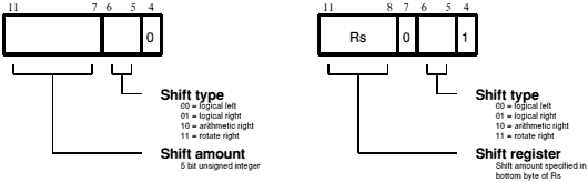
Shifts
Shifts are detailed in the Shift types.
Note that the zero in bit 7 of an instruction with a register controlled shift is compulsory; a one in this bit will cause the instruction to be a multiply or an undefined instruction.
The immediate operand rotate field is a 4 bit unsigned integer which specifies a shift operation on the 8 bit immediate value. The immediate value is zero extended to 32 bits, and then subject to a rotate right by twice the value in the rotate field. This enables many common constants to be generated, for example all powers of 2. Another example is that the 8 bit constant may be aligned with the PSR flags (bits 0, 1, and 26 to 31). All the flags can thereby be initialised in one TEQP instruction.
Immediate operand rotates are detailed in the The barrel shifter.
Note that the CPU takes certain actions whenever the destination or any operand is R15. These are as follows:
If R15 is the destination register, and the S bit is not set, the PC is overwritten, but not the PSR.
If the S bit is set, then the PC is overwritten, and also all bits of the PSR that are unprotected in the current mode; thus in User mode the N, Z, C and V flags are overwritten, whereas in other modes the entire PSR is overwritten.
R15 will always contain the value of the PC, which will be the address of the instruction, plus 8 or 12 bytes due to instruction prefetching. If the shift amount is specified in the instruction, the PC will be 8 bytes ahead. If a register is used to specify the shift amount, the PC will be 8 bytes ahead when used as Rs, and 12 bytes ahead when used as Rn or Rm.
R15 may or may not contain the values of the PSR flags as they were at the completion of the previous instruction, depending on which operand position it occupies:
These opcodes should not be used in 32 bit modes. You should instead use the new PSR transfer functions. When used in a privileged mode, TEQP moves the SPSR for the current mode to the CPSR.
You must not use R15 as the shift register.
If R15 is the destination register, and the S bit is not set, the PC is overwritten, but not the CPSR. This is what you would expect as an extension of the 26 bit behaviour.
If the destination register is R15 and the S bit is set, then as well as writing the result to the PC, the SPSR for the current mode is moved to the CPSR. This is again what you would expect as an extension of the 26 bit behaviour.
; Simple use of a one operand instruction:
        MVN     R2,R3           ; R2 is set to the bitwise inverse of the
                                ; contents of R3.

; Simple uses of instructions that does not write a result:
        CMP     R0,R1           ; Compare the contents of R0 with R1

        CMP     R0,#&80         ; Compare the contents of R0 with &80

        TEQS    R4,#3           ; Test R4 for equality with 3
                                ; (The S is in fact redundant as the assembler
                                ; inserts it automatically)

; Simple use of a two operand instruction:
        ADD     R0,R1,R2        ; R0=R1+R2

; Conditional execution of an instruction:
        ADDEQ   R2,R4,R5        ; If the Z flag is set make R2:=R4+R5

; Use of the S bit to alter the PSR:
        ADDS    R0,R1,#1        ; R0=R1+1, and set N,Z,C,V

; Use of a register specified shift:
        SUB     R4,R5,R7,LSR R2 ; Logical right shift R7 by the number in
                                ; the bottom byte of R2, subtract the result
                                ; from R5, and put the answer into R4
                                ; Use of an immediate shift:
        MOV     R0,R1,LSL#2     ; The contents of R1 are shifted left by
                                ; 2 bits and transferred to R0.

; Using ADC to implement multi-word additions. For example a 64 bit ADD:
        ADDS    R4,R2,R0        ; Add least significant 32 bits updating carry
        ADC     R5,R3,R1        ; Add most significant 32 bits and carry
                                ; from previous

; Using SBC to implement multi-word subtractions. For example:
        SUBS    R4,R2,R0        ; Do least significant word of subtraction
        SBC     R5,R3,R1        ; Do most significant word, taking account
                                ; of the borrow. This does the 64 bit
                                ; subtraction (R5,R4)=(R3,R2)-(R1,R0)

; Changing to user mode and returning from a subroutine:
        ; Assume non-user mode here
        TEQP    R15,#0          ; Change to user mode and clear N,Z,C,V,I,F
                                ; NB R15 is here in the Rn position,
                                ; so it comes without the PSR flags
        MOV     R0,R0           ; No-op to avoid mode change hazard
        MOV     PC,R14          ; Return from subroutine
                                ; (R14 is a banked register)

; Returning from a subroutine and restoring the PSR:
        MOVS    PC,R14          ; return from subroutine and restore the PSR
Instructions for accessing the CPSR and SPSR registers
These instructions are not available on ARM2 and ARM3 series processors
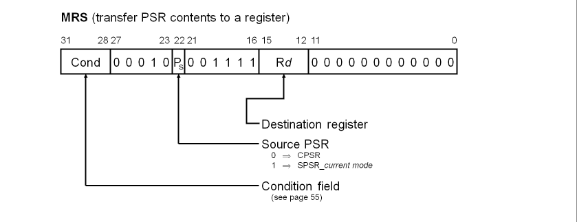
MRS«cond» Rd,psr
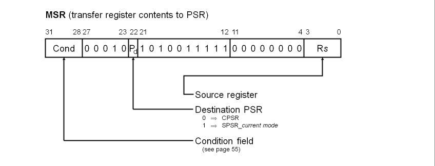
MSR«cond» psr,Rm
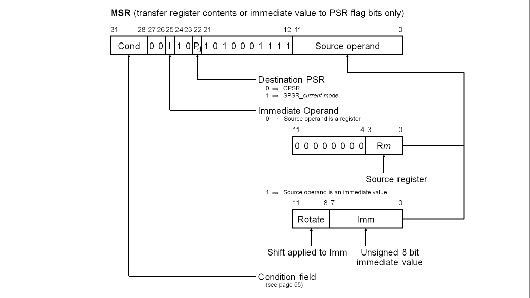
MSR«cond» psrf,Rm
MSR«cond» psrf,#expression
where:
| «cond» | is a two-character condition mnemonic; see the chapter entitled The condition field. |
| Rd & Rm | are expressions evaluating to a valid ARM register number other than R15. |
| psr | is CPSR, CPSR_all, SPSR or SPSR_all.
(CPSR and CPSR_all are synonyms, as are SPSR and SPSR_all.) |
| psrf | is CPSR_flg or SPSR_flg. The most significant four bits of Rm or #expression are written to the N, Z, C and V flags respectively. |
| #expression | is an expression symbolising a 32 bit value.
If #expression is used, ObjAsm will attempt to match the expression by generating a shifted immediate 8-bit field. If this is impossible, it will give an error. |
These instructions allow access to the CPSR and SPSR registers:
Alternatively, the MSR instruction can write to the condition code flags of the CPSR or SPSR_current mode register without affecting its control bits:
The instructions are encoded using the CMN, CMP, TEQ and TST instructions without the S flag set.
The instruction is only executed if the condition is true. The various conditions are defined in the The condition field.
These instructions are not available on ARM2 and ARM3 series processors.
On ARM6 series processors and later, they are available in all modes and configurations. However, we recommend that you avoid using these instructions, as you will lose backwards compatibility with older ARMs. Indeed, in the 26 bit modes used by RISC OS (except when handling FIQs), you can access the PSR just as you always have - for example, with TEQP.
In user mode, the control bits of the CPSR are protected from change, so only the condition code flags of the CPSR can be changed. In other (privileged) modes the entire CPSR can be changed.
R15 must not be specified as the source or destination register.
You must not attempt to access the SPSR in user mode, as no such register exists.
Not all bits of the PSR are defined (e.g. only N, Z, C, V, I, F and M[4:0] are defined for the ARM 6 and 7 series). The remaining ones (bits 27-8 and 5 in the ARM 6 and 7 series) are reserved for use in future versions of the ARM. The ensure future compatibility, the following rules should be observed:
You should therefore use a read-modify-write strategy when altering the control bits of any PSR register. This involves transferring the appropriate PSR register to a general register using the MRS instruction, changing only the relevant bits, and then transferring the modified value back to the PSR register using the MSR instruction.
For example, to perform a mode change:
        MRS     R0,CPSR                 ; Take a copy of the PSR
        BIC     R0,R0,#0x1F             ; Clear the mode bits
        ORR     R0,R0,#new_mode         ; Set bits for new mode
        MSR     CPSR,R0                 ; Write back the modified CPSR,
                                        ; changing mode
When you wish simply to change the condition flags in a PSR, you can write an immediate value directly to the flag bits without disturbing the control bits. For example, the following instruction sets the N, Z, C and V flags:
        MSR     CPSR_flg,#0xF0000000    ; Set all the flags regardless
                                        ; of their previous state
                                        ; (does not affect any control bits)
You must not attempt to write an 8 bit immediate value into the whole PSR, since such an operation cannot preserve the reserved bits.
In user mode the instructions behave as follows:
        MSR     CPSR_all,Rm             ; CPSR[31:28] <- Rm[31:28]
        MSR     CPSR_flg,Rm             ; CPSR[31:28] <- Rm[31:28]

        MSR     CPSR_flg,#0xA0000000    ; CPSR[31:28] <- 0xA
                                        ;  (i.e. set N,C; clear Z,V)

        MRS     Rd,CPSR                 ; Rd[31:0] <- CPSR[31:0]
In privileged modes the instructions behave as follows:
        MSR     CPSR_all,Rm             ; CPSR[31:0]  <- Rm[31:0]
        MSR     CPSR_flg,Rm             ; CPSR[31:28] <- Rm[31:28]

        MSR     CPSR_flg,#0x50000000    ; CPSR[31:28] <- 0x5
                                        ;  (i.e. set Z,V; clear N,C)

        MRS     Rd,SPSR                 ; Rd[31:0] <- SPSR[31:0]
        MSR     SPSR_all,Rm             ; SPSR_<mode>[31:0]  <- Rm[31:0]
        MSR     SPSR_flg,Rm             ; SPSR_<mode>[31:28] <- Rm[31:28]

        MSR     SPSR_flg,#0xC0000000    ; SPSR_<mode>[31:28] <- 0xC
                                        ;  (i.e. set N,Z; clear C,V)
        MRS     Rd,SPSR                 ; Rd[31:0] <- SPSR_<mode>[31:0]
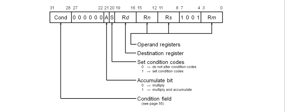
Instructions for performing integer multiplication, giving a 32 bit result
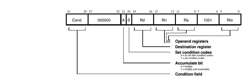
MUL«cond»«S» Rd,Rm,Rs
MLA«cond»«S» Rd,Rm,Rs,Rn
| «cond» | is a two-character condition mnemonic; see the chapter entitled The condition field. |
| «S» | means to set the PSR's condition codes from the operation. |
| Rd, Rm, Rs & Rn | are expressions evaluating to a valid ARM register number.
(Rd must not be R15 and must not be the same as Rm.) |
The multiply and multiply-accumulate instructions use a 2 bit Booth's algorithm to perform integer multiplication. They give the least significant 32 bits of the product of two 32 bit operands, and may be used to synthesize higher precision multiplications.
The multiply form of the instruction gives Rd:=Rm×Rs. Rn is ignored, and should be set to zero for compatibility with possible future upgrades to the instruction set.
The multiply-accumulate form gives Rd:=Rm×Rs+Rn, which can save an explicit ADD instruction in some circumstances.
The results of a signed multiply and of an unsigned multiply of 32 bit operands differ only in the upper 32 bits; the low 32 bits are identical. As these instructions only produce those low 32 bits, they can be used with operands which may be considered as either signed (2's complement) or unsigned integers.
The instruction is only executed if the condition is true. The various conditions are defined in the The condition field.
Setting the PSR flags is optional, and is controlled by the S bit in the instruction. The N and Z flags are set correctly on the result (N is equal to bit 31 of the result, Z is set if and only if the result is zero), the V flag is unaffected by the instruction, and the C flag is set to a meaningless value.
Because of the way the Booth's algorithm has been implemented, you should avoid certain combinations of operand registers. (ObjAsm will issue a warning if you overlook these restrictions.)
The destination register Rd must not be the same as the Rm operand register, as Rd is used to hold intermediate values, and Rm is used repeatedly during the multiply.
The destination register Rd must also not be R15.
All other register combinations will give correct results, and Rd, Rn and Rs may use the same register when required.
R15 must not be used as any of Rd, Rm, Rn or Rs.
        MUL     R1,R2,R3                ; R1:=R2*R3

        MLAEQS  R1,R2,R3,R4             ; conditionally R1:=R2*R3+R4,
                                        ; setting condition codes
The multiply instruction may be used to synthesize higher precision multiplications, for instance to multiply two 32 bit integers and generate a 64 bit result:
mul64
        MOV     a1,A,LSR #16            ; a1:=top half of A
        MOV     D,B,LSR #16             ; D:=top half of B
        BIC     A,A,a1,LSL #16          ; A:=bottom half of A
        BIC     B,B,D,LSL #16           ; B:=bottom half of B
        MUL     C,A,B                   ; Low section of result
        MUL     B,a1,B                  ; ) Middle sections
        MUL     A,D,A                   ; ) of result
        MUL     D,a1,D                  ; High section of result
        ADDS    A,B,A                   ; Add middle sections (couldn't use
                                        ;  MLA as we need C correct)
        ADDCS   D,D,#&10000             ; Carry from above add
        ADDS    C,C,A,LSL #16           ; C is now bottom 32 bits of product
        ADC     D,D,A,LSR #16           ; D is top 32 bits
(A, B are registers containing the 32 bit integers; C, D are registers for the 64 bit result; a1 is a temporary register. A and B are overwritten during the multiply.)
Note that more recent ARM processors have a single instruction to do just this; see the next section.
Instructions for performing integer multiplication, giving a 64 bit result
This instruction is only available in 32 bit mode on the ARM7M series or later
UMULL«cond»«S» RdLo,RdHi,Rm,Rs
SMULL«cond»«S» RdLo,RdHi,Rm,Rs
UMLAL«cond»«S» RdLo,RdHi,Rm,Rs
SMLAL«cond»«S» RdLo,RdHi,Rm,Rs
| «cond» | is a two-character condition mnemonic; see the chapter entitled The condition field. |
| «S» | means to set the PSR's condition codes from the operation. |
| RdLo, RdHi, Rm & Rs | are expressions evaluating to a valid ARM register number other than R15. |
The multiply long instructions perform integer multiplication on two 32 bit operands, and produce a 64 bit result. The multiplication can be signed or unsigned, which - with optional accumulate - gives rise to four variations.
The multiply forms of the instruction (UMULL and SMULL) give a 64 bit result of the form RdHi,RdLo:=Rm×Rs.
The multiply-accumulate forms (UMLAL and SMLAL) give Rd:=Rm×Rs+Rn, which can save an explicit ADD instruction in some circumstances.
The lower 32 bits of the result and of the accumulator (where used) are held in RdLo, and the upper 32 bits in RdHi.
The unsigned forms of the instruction (UMULL and UMLAL) treat all four registers as unsigned numbers. The signed forms (SMULL and SMLAL) treat the two operand registers as 2's complement signed 32 bit numbers, and the two destination registers as a 2's complement signed 64 bit number.
The instruction is only executed if the condition is true. The various conditions are defined in the The condition field.
This instruction was first introduced on the ARM7M series of processor, and is only available in 32 bit modes. This instruction is therefore unlikely to be of use under RISC OS.
Setting the PSR flags is optional, and is controlled by the S bit in the instruction. The N and Z flags are set correctly on the result (N is equal to bit 31 of the result, Z is set if and only if the result is zero), and the V and C flags are set to a meaningless value.
R15 must not be used as any of RdHi, RdLo, Rm or Rs.
RdHi, RdLo and Rm must all specify different registers.
        UMULL   R1,R4,R2,R3          ; R1,R4:=R2*R3

        UMLALS  R1,R5,R2,R3          ; R1,R5:=R2*R3+R1,R5,
                                     ; also setting condition codes
Instructions for loading or storing single bytes or words of data
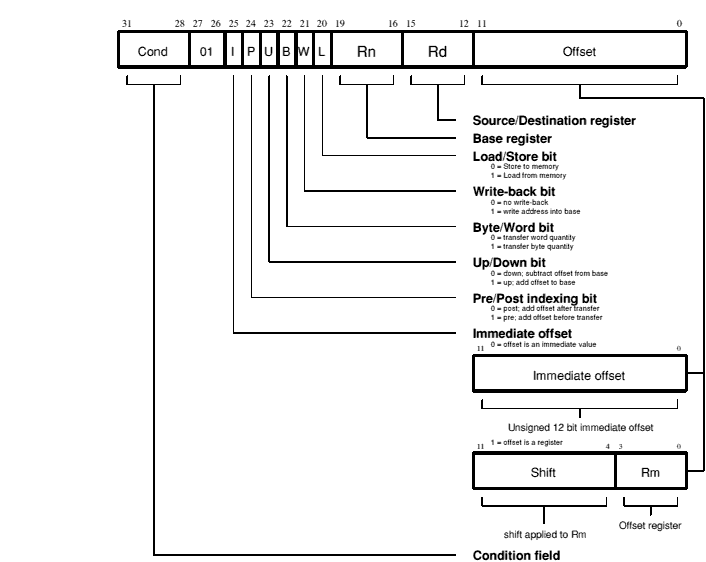
LDR|STR«cond»«B»«T» Rd,address
| LDR | loads from memory into a register. | ||||||||||
| STR | stores from a register into memory. | ||||||||||
| «cond» | is a two-character condition mnemonic; see the chapter entitled The condition field. | ||||||||||
| «B» | means to transfer a byte, otherwise a word is transferred. | ||||||||||
| «T» | means to set the W bit in a post-indexed instruction, forcing non-privileged mode for the transfer cycle. T is not allowed when a pre-indexed addressing mode is specified or implied. | ||||||||||
| Rd | is an expression evaluating to a valid ARM register number. | ||||||||||
| address | can be:
Rn and Rm are expressions evaluating to a valid ARM register number. Note if Rn is R15 then ObjAsm will subtract 8 from the offset value to allow for ARM pipelining. shift is a general shift operation (see the chapter entitled Shift types), but note that the shift amount may not be specified by a register. «!» if present sets the W bit to write-back the base register. |
The single data transfer instructions are used to load or store single bytes or words of data. The memory address used in the transfer is calculated by adding an offset to or subtracting an offset from a base register. The result of this calculation may be written back into the base register if 'auto-indexing' is required. If the contents of the base are not destroyed by other instructions, the continued use of LDR (or STR) with write back will continually move the base register through memory in steps given by the index value. Note that ! is invalid for post-indexed addressing, as write back is automatic in this case.
The instruction is only executed if the condition is true. The various conditions are defined in the The condition field.
For register to register transfers, see the chapter entitled Data processing, particularly the MOV instruction.
The offset from the base may be either a 12 bit unsigned binary immediate value in the instruction, or a second register (possibly shifted in some way). The offset may be added to (U=1) or subtracted from (U=0) the base register Rn. The offset modification may be performed either before (pre-indexed, P=1) or after (post-indexed, P=0) the base is used as the transfer address.
The W bit gives optional auto increment and decrement addressing modes. The modified base value may be written back into the base (W=1), or the old base value may be kept (W=0). In the case of post-indexed addressing, the write back bit is redundant, since the old base value can be retained by setting the offset to zero. Therefore post-indexed data transfers always write back the modified base. The only use of the W bit in a post-indexed data transfer is in privileged mode code; depending on the processor, setting the W bit either forces the TRANS pin to go LOW or forces non-privileged mode for the transfer, allowing the operating system to generate a user address in a system where the memory management hardware makes suitable use of this hardware.
The 8 shift control bits are described in the Data processing, but the register specified shift amounts are not available in this instruction class.
This instruction class may be used to transfer a byte (B=1) or a word (B=0) between an ARM register and memory.
A byte load (LDRB) expects the data on bits 0 to 7 if the supplied address is on a word boundary, on bits 8 to 15 if it is a word address plus one byte, and so on. The selected byte is placed in the bottom 8 bits of the destination register, and the remaining bits of the register are filled with zeroes.
A byte store (STRB) repeats the bottom 8 bits of the source register four times across the data bus. The external memory system should activate the appropriate byte subsystem to store the data.
A word load (LDR) or word store (STR) should generate a word aligned address. Using a non-word-aligned addresses has non-obvious and unspecified results.
These instructions will never cause the PSR to be modified, even when Rd or Rn is R15.
If R15 is specified as the base register (Rn), the PC is used without the PSR flags. When using the PC as the base register you must remember that it contains an address 8 bytes on from the address of the current instruction.
If R15 is specified as the register offset (Rm), the value presented will be the PC together with the PSR.
When R15 is the source register (Rd) of a register store (STR) instruction, the value stored will be the PC together with the PSR. The stored value of the PC will be 12 bytes on from the address of the instruction. A load register (LDR) with R15 as Rd will change only the PC, and the PSR will be unchanged.
On an ARM2 or ARM3 processor, if the address used for the transfer (ie the unmodified contents of the base register for post-indexed addressing, or the base modified by the offset for pre-indexed addressing) has a logic one in any of the bits 26 to 31, the transfer will not take place and the address exception trap will be taken.
Later versions of the ARM do not generate address exceptions when in a 32 bit configuration (as used by RISC OS from very soon after reset), even when running in 26 bit modes.
Note that it is only the address actually used for the transfer which is checked. A base containing an address outside the legal range may be used in a pre-indexed transfer if the offset brings the address within the legal range, and likewise a base within the legal range may be modified by post-indexing to outside the legal range without causing an address exception.
A transfer to or from a legal address may still cause problems for a memory management system. For instance, in a system which uses virtual memory the required data may be absent from main memory. The memory manager can signal a problem by taking the processor ABORT pin HIGH, whereupon the data transfer instruction will be prevented from changing the processor state and the Data Abort trap will be taken. It is up to the system software to resolve the cause of the problem, then the instruction can be restarted and the original program continued.
R15 must not be used as the register offset (Rm).
If R15 is specified as the base register (Rn), you must not use write-back - including post indexing.
For a post-indexed LDR or STR, Rm and Rn must not be the same register.
When using write-back - including post indexing -Rd and Rn must not be the same register.
        STR     R1,[BASE,INDEX]!        ; store R1 at BASE+INDEX (both of
                                        ; which are registers) and write
                                        ; back address to BASE

        STR     R1,[BASE],INDEX         ; store R1 at BASE and writeback
                                        ; BASE+INDEX to BASE

        LDR     R1,[BASE,#16]           ; load R1 from contents of BASE+16.
                                        ; Don't write back

        LDR     R1,[BASE,INDEX,LSL #2]  ; load R1 from contents of
                                        ; BASE+INDEX*4

        LDREQB  R1,[BASE,#5]            ; conditionally load byte at BASE+5
                                        ; into R1 bits 0 to 7, filling bits
                                        ; 8 to 31 with zeroes

        STR     R1,PLACE                ; generate PC relative offset to
                                        ; address PLACE
        More instructions

PLACE
Instructions for loading or storing any subset of the currently visible registers
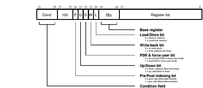
LDM|STM«cond»FD|ED|FA|EA|IA|IB|DA|DB Rn«!»,Rlist«^»
| LDM | loads from memory into register(s). |
| STR | stores from register(s) into memory. |
| «cond» | is a two-character condition mnemonic; see the chapter entitled The condition field. |
| Rn | is an expression evaluating to a valid ARM register number. |
| Rlist | is either a comma-separated list of registers and/or of register ranges indicated by hyphens, all enclosed in {} (e.g. {R0,R2-R7,R10}); or an expression evaluating to the 16 bit operand. |
| «!» | if present sets the W bit to write-back the base register. |
| «^» | if present sets the S bit to load the PSR with the PC, or forces storing of user bank registers when in a non-user mode. |
There are different assembler mnemonics for each of the addressing modes. There are alternative forms for each mnemonic: one form is intended for use with stacks, and describes the type of stack the addressing mode supports; the other form merely describes the instructions functionality. The equivalencies between the names and the values of the bits in the instruction are:
| Name | Stack | Other | L bit | P bit | U bit |
|---|---|---|---|---|---|
| pre-increment load | LDMED | LDMIB | 1 | 1 | 1 |
| post-increment load | LDMFD | LDMIA | 1 | 0 | 1 |
| pre-decrement load | LDMEA | LDMDB | 1 | 1 | 0 |
| post-decrement load | LDMFA | LDMDA | 1 | 0 | 0 |
| pre-increment store | STMFA | STMIB | 0 | 1 | 1 |
| post-increment store | STMEA | STMIA | 0 | 0 | 1 |
| pre-decrement store | STMFD | STMDB | 0 | 1 | 0 |
| post-decrement store | STMED | STMDA | 0 | 0 | 0 |
In the stacking forms of the mnemonics (FD, ED, FA and EA), the F and E refer to a full or empty stack, and the A and D refer to an ascending or descending stack:
The other forms of the mnemonics (IA, IB, DA and DB) simply mean Increment After, Increment Before, Decrement After, and Decrement Before.
Block data transfer instructions are used to load (LDM) or store (STM) any subset of the currently visible registers from or to memory. They support all possible stacking modes, maintaining full or empty stacks which can grow up or down memory, and are very efficient instructions for saving or restoring context, or for moving large blocks of data around main memory.
The instruction is only executed if the condition is true. The various conditions are defined in the The condition field.
The instruction can cause the transfer of any registers in the current bank (and non-user mode programs can also transfer to and from the user bank, see below). The register list is a 16 bit field in the instruction, with each bit corresponding to a register. A 1 in bit 0 of the register field will cause R0 to be transferred, a 0 will cause it not to be transferred; similarly bit 1 controls the transfer of R1, and so on.
Any subset of the registers, or all the registers, may be specified. The only restriction is that the register list must not be empty.
The transfer addresses are determined by the contents of the base register (Rn), the pre/post bit (P) and the up/down bit (U). The registers are stored such that the lowest register is always at the lowermost address in memory, the highest register is always at the uppermost address, and the others are stored in numerical order between them.
(As an aside, this means that instruction sequences such as:
STMIA   R0,{R1,R2}
LDMIA   R0,{R2,R1}
do not swap the contents of R1 and R2.)
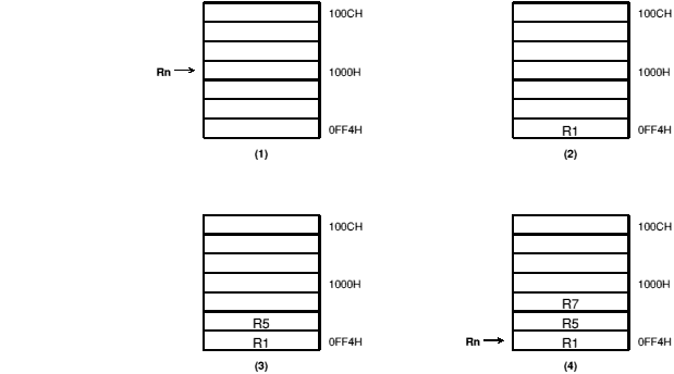
By way of illustration, consider the transfer of R1, R5 and R7 in the case where Rn=1000H and write back of the modified base is required (W=1). The figures below show the sequence of register transfers, the addresses used, and the value of Rn after the instruction has completed.
(In all cases, had write back of the modified base not been required (W=0), Rn would have retained its initial value of 1000H unless it was also in the transfer list of a load multiple register instruction, when it would have been overwritten with the loaded value.)
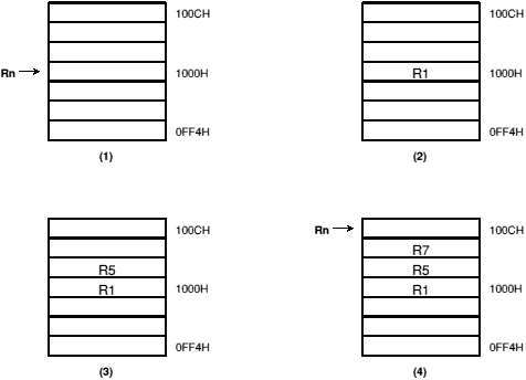
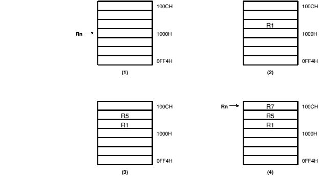
Pre-increment addressing
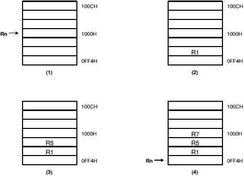
Post-decrement addressing
Whenever R15 is stored to memory, the value transferred is the PC together with the PSR flags. The stored value of the PC will be 12 bytes on from the address of the STM instruction.
If R15 is in the transfer list of a load multiple (LDM) instruction the PC is overwritten, and the effect on the PSR is controlled by the S bit. If the S bit is 0 the PSR is preserved unchanged, but if the S bit is 1 the PSR will be overwritten by the corresponding bits of the loaded value. In user mode, however, the I, F, M0 and M1 bits are protected from change whatever the value of the S bit. The mode at the start of the instruction determines whether these bits are protected, and the supervisor may return to the user program, re-enabling interrupts and restoring user mode with one LDM instruction.
For STM instructions the S bit is redundant as the PSR is always stored with the PC whenever R15 is in the transfer list. For LDM instructions the S bit is redundant if R15 is not in the transfer list.
In both the above cases, the S bit is instead used to force transfers in non-user modes to use the user register bank instead of the current register bank. This is useful for saving and restoring the user state on process switches. You must not use write back of the base when forcing user bank transfer.
For an LDM instruction, you must take care not to read from a banked register during the following cycle; if in doubt insert a no-op.
When the base is the PC, the PSR bits will be used to form the address as well, so unless all interrupts are enabled and all flags are zero an address exception will occur. Also, write back is never allowed when the base is the PC (setting the W bit will have no effect).
When writeback is specified, the base is written back at the end of the second cycle of the instruction. During a STM, the first register is written out at the start of the second cycle. A STM which includes storing the base, with the base as the first register to be stored, will therefore store the unchanged value, whereas with the base second or later in the transfer order, will store the modified value. An LDM will always overwrite the updated base if the base is in the list.
Thus, if the base register is the lowest-numbered register in the list, its original value is stored. Otherwise, its written back value is stored.
On an ARM2 or ARM3 processor, if the address of the first transfer falls outside the legal address space (ie has a 1 somewhere in bits 26 to 31), an address exception trap will be taken. The instruction will first complete in the usual number of cycles, though an STM will be prevented from writing to memory. The processor state will be the same as if a data abort had occurred on the first transfer cycle (see next section).
Only the address of the first transfer is checked in this way; if subsequent addresses over- or under-flow into illegal address space they will be truncated to 26 bits but will not cause an address exception trap.
Later versions of the ARM do not generate address exceptions when in a 32 bit configuration (as used by RISC OS from very soon after reset), even when running in 26 bit modes.
Some legal addresses may be unacceptable to a memory management system, and the memory manager can indicate a problem with an address by taking the ABORT signal HIGH. This can happen on any transfer during a multiple register load or store, and must be recoverable if the ARM is to be used in a virtual memory system.
If the abort occurs during a store multiple instruction, ARM takes little action until the instruction completes, whereupon it enters the data abort trap. The memory manager is responsible for preventing erroneous writes to the memory. The only change to the internal state of the processor will be the modification of the base register if write-back was specified, and this must be reversed by software (and the cause of the abort resolved) before the instruction may be retried.
When ARM detects a data abort during a load multiple instruction, it modifies the operation of the instruction to ensure that recovery is possible
The data abort trap is taken when the load multiple has completed, and the system software must undo any base modification (and resolve the cause of the abort) before restarting the instruction.
For an STM instruction where R15 is in the transfer list, the PC is stored, but the CPSR is not stored to the current mode's SPSR. (The intuitive extension of the 26 bit behaviour would be for the CPSR to be stored.)
For an LDM instruction where R15 is in the transfer list, if the S bit is set then as well as overwriting the PC, the SPSR for the current mode is moved to the CPSR. This is what you would expect as an extension of the 26 bit behaviour.
The S bit must not be set for instructions that are to be executed in user mode.
You must not use R15 as the base register.
        LDMFD   SP!,{R0,R1,R2}  ; unstack 3 registers

        STMIA   BASE,{R0-R15}   ; save all registers
These instructions may be used to save state on subroutine entry, and restore it efficiently on return to the calling routine:
        STMED   SP!,{R0-R3,R14} ; save R0 to R3 to use as workspace
                                ; and R14 for returning

        BL somewhere             ; this nested call will overwrite R14

        LDMED   SP!,{R0-R3,R15}^; restore workspace and return
                                ; (also restoring PSR flags)
Instruction for swapping atomically between a register and external memory
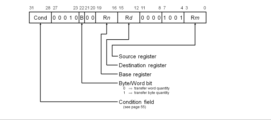
SWP «cond»«B» Rd,Rm,[Rn]
| «cond» | is a two-character condition mnemonic; see the chapter entitled The condition field. |
| «B» | means to transfer a byte, otherwise a word is transferred. |
| Rd, Rm & Rn | are expressions evaluating to a valid ARM register number. |
The data swap instruction is used to swap atomically a byte or word quantity between a register and external memory. It is implemented as a memory read followed by a memory write to the same address, which are 'locked' together. The processor cannot be interrupted until both operations have completed, and the memory manager is warned to treat them as inseparable. This instruction is particularly useful for implementing software semaphores.
The swap address is determined by the contents of the base register (Rn). The processor first reads the contents of the swap address. It then writes the contents of the source register (Rm) to the swap address, and stores the old memory contents in the destination register (Rd). The same register may be specified as both the source and destination; its contents are correctly swapped with memory.
The LOCK output goes HIGH for the duration of the read and write operations to signal to the external memory manager that they are locked together, and should be allowed to complete without interruption. This is important in multi-processor systems, where the swap instruction is the only indivisible instruction which may be used to implement semaphores. Control of the memory must not be removed from a processor while it is performing a locked operation.
The SWP instruction is not supported by the ARM2 processor, but is available in the ARM3, in the ARM2aS macrocell (as used for the ARM250 chip in the Acorn A3010, 3020 and A4000), and on the ARM6 series and later.
This instruction may be used to swap a byte (B=1) or a word (B=0) between a register and memory. The SWP instruction is implemented as a LDR followed by a STR, and the action of these is as described in Single data transfer (LDR, STR).
You must not use R15 as an operand (Rd, Rn or Rm in a SWP instruction.
If the address used for the swap is unacceptable to a memory management system, the internal MMU or external memory manager can flag the problem by driving ABORT HIGH. This can happen on either the read or the write cycle (or both), and in either case, the Data Abort trap will be taken. It is up to the system software to resolve the cause of the problem. Once this has been done, the instruction can be restarted and the original program continued.
        SWP     R0,R1,[R2]      ; load R0 with the word addressed by R2,
                                ; and then store R1 at the same address

        SWPB    R2,R3,[R4]      ; load R2 with the byte addressed by R4,
                                ; and then store bits 0 to 7 of R3 at the
                                ; same address

        SWPEQ   R0,R0,[R1]      ; conditionally swap the word addressed
                                ; by R1 with the contents of R0
Instruction for entering supervisor mode in a controlled manner
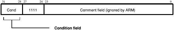
SWI«cond» expression
| «cond» | is a two-character condition mnemonic; see the chapter entitled The condition field. |
| expression | is evaluated and placed in the comment field as a SWI number (which is ignored by ARM). |
The software interrupt instruction is used to enter supervisor mode in a controlled manner. The instruction causes the software interrupt trap to be taken, which effects the mode change. The PC is then forced to the SWI vector. If this address is suitably protected (by external memory management hardware) from modification by the user, a fully protected operating system may be constructed.
The instruction is only executed if the condition is true. The various conditions are defined in the The condition field.
The PC and PSR are saved in R14_svc upon entering the software interrupt trap, with the PC adjusted to point to the word after the SWI instruction. MOVS R15,R14_svc will return to the calling program, and restore the PSR.
Note that the link mechanism is not re-entrant, so if the supervisor code wishes to use software interrupts within itself it must first save a copy of the return address.
The bottom 24 bits of the instruction are ignored by ARM, and may be used to communicate information to the supervisor code. For instance, the supervisor may look at this field and use it to index into an array of entry points for routines which perform the various supervisor functions (as in RISC OS).
The CPSR is saved in SPSR_svc. The MOVS R15,R14_svc instruction used to return to the supervisor restores the CPSR from SPSR_svc. This is what you would expect as an extension of the 26 bit behaviour.
        SWI     Read                    ; get next character from read stream

        SWI     WriteI+"k"              ; output a "k" to the write stream

        SWINE   0                       ; conditionally call supervisor
                                        ; with 0 in comment field
The above examples assume that suitable supervisor code exists at the SWI vector address, for instance:
        B       Supervisor              ; SWI entry point

EntryTable                              ; addresses of supervisor routines
        DCD     ZeroRtn
        DCD     ReadCRtn
        DCD     WriteIRtn
        ...
Zero    EQU     0
ReadC   EQU     256
WriteI  EQU     512

Supervisor

; SWI has routine required in bits 8-23, data (if any) in bits 0-7.
; Assumes R13_svc points to a suitable stack.

        STM     R13,{R0-R2,R14}         ; Save work registers and return
                                        ; address
        BIC     R0,R14,#&FC000003       ; Clear PSR bits
        LDR     R0,[R0,#-4]             ; Get SWI instruction
        BIC     R0,R0,#&FF000000        ; Clear top 8 bits
        MOV     R1,R0,LSR #8            ; Get routine offset
        ADR     R2,EntryTable           ; Get start address of entry table
        LDR     R15,[R2,R1,LSL #2]      ; Branch to appropriate routine

WriteIRtn                               ; Enter with character in R0 bits 0-7
...
        LDM     R13,{R0-R2,R15}^        ; Restore workspace and return.
Instruction for telling a coprocessor to perform some internal operation
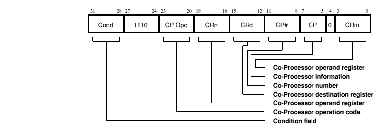
CDP«cond» CP#,operation,CRd,CRn,CRm«,info»
| «cond» | is a two-character condition mnemonic; see the chapter entitled The condition field. |
| CP# | is the unique number of the required coprocessor, which must be a symbol defined via the CP directive. |
| operation | is evaluated to a constant and placed in the CP Opc field. |
| CRd, CRn & CRm | are expressions evaluating to a valid coprocessor register number, which must be a symbol defined via the CN directive. |
| info | where present is evaluated to a constant and placed in the CP field. |
This instruction is used to tell a coprocessor to perform some internal operation. No result is communicated back to ARM, and it will not wait for the operation to complete. The coprocessor could contain a queue of such instructions awaiting execution, and their execution can overlap other ARM activity, allowing the coprocessor and ARM to perform independent tasks in parallel.
The instruction is only executed if the condition is true. The various conditions are defined in the The condition field.
Only bit 4 and bits 24 to 31 are significant to ARM; the remaining bits are used by coprocessors. The above field names are used by convention, and particular coprocessors may redefine the use of all fields except CP# as appropriate. The CP# field is used to contain an identifying number (in the range 0 to 15) for each coprocessor, and a coprocessor will ignore any instruction which does not contain its number in the CP# field.
The conventional interpretation of the instruction is that the coprocessor should perform an operation specified in the CP Opc field (and possibly in the CP field) on the contents of CRn and CRm, and place the result in CRd.
Current ARM chips have a fault in the implementation of CDP which will cause a Software Interrupt to take the Undefined Instruction trap if the SWI is the next instruction after the CDP. This problem only arises when a hardware coprocessor is attached to the system, but if it is ever intended to add hardware to support a CDP (rather than trapping to an emulator) the sequence CDP SWI should be avoided.
        CDP     p1,10,CR1,CR2,CR3       ; Request coprocessor 1 to do
                                        ; operation 10 on CR2 and CR3,
                                        ; and put the result in CR1.

        CDPEQ   p2,5,CR1,CR2,CR3,2      ; If Z flag is set, request
                                        ; coprocessor 2 to do operation 5
                                        ; (type 2) on CR2 and CR3,
                                        ; and put the result in CR1.
Instructions for transferring data between the coprocessor and main memory
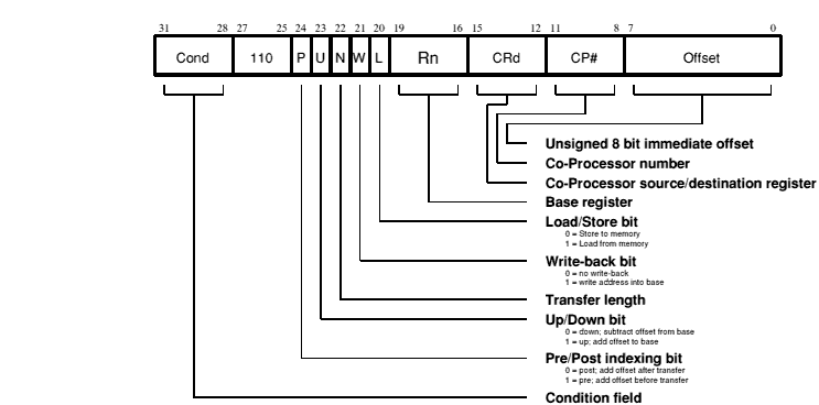
LDC|STC«cond»«L» CP#,CRd,address
| LDC | loads from memory to coprocessor (L=1). | ||||||
| STC | stores from coprocessor to memory (L=0). | ||||||
| «L» | when present perform long transfer (N=1), otherwise perform short transfer (N=0). | ||||||
| «cond» | is a two-character condition mnemonic; see the chapter entitled The condition field. | ||||||
| CP# | is the unique number of the required coprocessor, which must be a symbol defined via the CP directive. | ||||||
| CRd | is an expression evaluating to a valid coprocessor register number, which must be a symbol defined via the CN directive. | ||||||
| address | can be:
Rn is an expression evaluating to a valid ARM register number. Note if Rn is R15 then ObjAsm will subtract 8 from the offset value to allow for ARM pipelining. «!» if present sets the W bit to write-back the base register. |
These instructions are used to load (LDC) or store (STC) a subset of the coprocessor's registers directly to memory. ARM is responsible for supplying the memory address, and the coprocessor supplies or accepts the data and controls the number of words transferred.
The instruction is only executed if the condition is true. The various conditions are defined in the The condition field.
The CP# field is used to identify the coprocessor which is required to supply or accept the data, and a coprocessor will only respond if its number matches the contents of this field.
The CRd field and the N bit contain information for the coprocessor which may be interpreted in different ways by different coprocessors, but by convention CRd is the register to be transferred (or the first register where more than one is to be transferred), and the N bit is used to choose one of two transfer length options. For instance N=0 could select the transfer of a single register, and N=1 could select the transfer of all the registers for context switching.
ARM is responsible for providing the address used by the memory system for the transfer, and the addressing modes available are a subset of those used in single data transfer instructions. Note, however, that the immediate offsets are 8 bits wide and specify word offsets for coprocessor data transfers, whereas they are 12 bits wide and specify byte offsets for single data transfers.
The 8 bit unsigned immediate offset is shifted left 2 bits and added to (U=1) or subtracted from (U=0) a base register (Rn); this calculation may be performed either before (P=1) or after (P=0) the base is used as the transfer address. The modified base value may be overwritten back into the base register (if W=1), or the old value of the base may be preserved (W=0). Note that post-indexed addressing modes require explicit setting of the W bit, unlike LDR and STR which always write-back when post-indexed.
The value of the base register, modified by the offset in a pre-indexed instruction, is used as the address for the transfer of the first word. The second word (if more than one is transferred) will go to or come from an address one word (4 bytes) higher than the first transfer, and the address will be incremented by one word for each subsequent transfer.
The base address should normally be a word aligned quantity. The bottom 2 bits of the address will appear on A[1:0] and might be interpreted by the memory system.
If Rn is R15, the value used will be the PC without the PSR flags, with the PC being the address of this instruction plus 8 bytes. Write-back to the PC is inhibited, and the W bit will be ignored.
If the address used for the first transfer is illegal the address exception mechanism will be invoked. Instructions which transfer multiple words will only trap if the first address is illegal; subsequent addresses will wrap around inside the 26 bit address space.
If the address is legal but the memory manager generates an abort, the data abort trap will be taken. The writeback of the modified base will take place, but all other processor state will be preserved. The coprocessor is partly responsible for ensuring that the data transfer can be restarted after the cause of the abort has been resolved, and must ensure that any subsequent actions it undertakes can be repeated when the instruction is retried.
If R15 is specified as the base register (Rn), you must not use write-back.
        LDC     p1,CR2,table            ; Load CR2 of coprocessor 1 from
                                        ; address table, using a PC relative
                                        ; address.

        STCEQL  p2,CR3,[R5,#24]!        ; Conditionally store CR3 of
                                        ; coprocessor 2 into an address
                                        ; 24 bytes up from R5, write this
                                        ; address back into R5, and use long
                                        ; transfer option (probably to store
                                        ; multiple words)
Note that though the address offset is expressed in bytes, the instruction offset field is in words. ObjAsm will adjust the offset appropriately.
Instructions for communicating information between ARM and a coprocessor
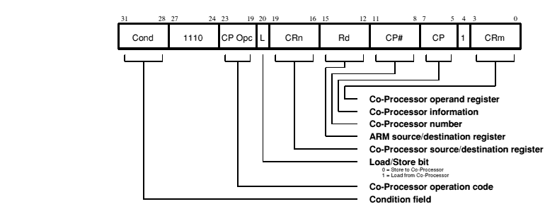
MCR|MRC«cond» CP#,operation,Rd,CRn,CRm«,info»
| MCR | moves from coprocessor to ARM register (L=1). |
| MRC | moves from ARM register to coprocessor (L=0). |
| «cond» | is a two-character condition mnemonic; see the chapter entitled The condition field. |
| CP# | is the unique number of the required coprocessor, which must be a symbol defined via the CP directive. |
| operation | is evaluated to a constant and placed in the CP Opc field. |
| Rd | is an expression evaluating to a valid ARM register number. |
| CRn & CRm | are expressions evaluating to a valid coprocessor register number, which must be a symbol defined via the CN directive. |
| info | where present is evaluated to a constant and placed in the CP field. |
These instructions are used to communicate information directly between ARM and a coprocessor. An example of a coprocessor to ARM register transfer (MCR) instruction would be a FIX of a floating point value held in a coprocessor, where the floating point number is converted into a 32 bit integer within the coprocessor, and the result is then transferred to an ARM register. A FLOAT of a 32 bit value in an ARM register into a floating point value within the coprocessor illustrates the use of an ARM register to coprocessor transfer (MRC).
An important use of this instruction is to communicate control information directly from the coprocessor into the ARM PSR flags. As an example, the result of a comparison of two floating point values within a coprocessor can be moved to the PSR to control the subsequent flow of execution.
Note that the ARM6 series and later have an internal coprocessor (#15) for control of on-chip functions. Accesses to this coprocessor are performed during coprocessor register transfers.
The instruction is only executed if the condition is true. The various conditions are defined in The condition field.
The CP# field is used, as for all coprocessor instructions, to specify which coprocessor is being called upon to respond.
The CP Opc, CRn, CP and CRm fields are used only by the coprocessor, and the interpretation presented here is derived from convention only. Other interpretations are allowed where the coprocessor functionality is incompatible with this one. The conventional interpretation is that the CP Opc and CP fields specify the operation the coprocessor is required to perform, CRn is the coprocessor register which is the source or destination of the transferred information, and CRm is a second coprocessor register which may be involved in some way which depends on the particular operation specified.
When a coprocessor register transfer to ARM has R15 as the destination, bits 31, 30, 29 and 28 of the transferred word are copied into the N, Z, C and V flags (respectively) of the PSR. The other bits of the transferred word are ignored, and the PC and other PSR flags are unaffected by the transfer.
A coprocessor register transfer from ARM with R15 as the source register will store the PC together with the PSR flags.
When a coprocessor register transfer to ARM has R15 as the destination, bits 31, 30, 29 and 28 of the transferred word are copied into the N, Z, C and V flags (respectively) of the CPSR. The other bits of the transferred word are ignored, and the PC and other PSR flags are unaffected by the transfer. This is what you would expect as an extension of the 26 bit behaviour.
A coprocessor register transfer from ARM with R15 as the source register will store the PC+12. Unlike the 26 bit behaviour, it does not store the CPSR to the coprocessor.
        MRC     2,5,R3,CR5,CR6          ; Request Co-Proc 2 to perform
                                        ; operation 5 on CR5 and CR6, and
                                        ; transfer the (single 32 bit word)
                                        ; result back to R3.

        MRCEQ   3,9,R3,CR5,CR6,2        ; Conditionally request Co-Proc 2 to
                                        ; perform operation 9 (type 2) on
                                        ; CR5 and CR6, and transfer the
                                        ; result back to R3.
Undefined instructions

At present ObjAsm has no mnemonics for generating these instructions. If they are adopted in the future for some specified use, suitable mnemonics will be added to ObjAsm. Until such time, these instructions should not be used.
If the condition is true, the undefined instruction trap will be taken.
Note that the undefined instruction mechanism involves offering these instructions to any coprocessors which may be present, and all coprocessors must refuse to accept them by letting CPA float HIGH.
(Note that some instruction codes are not defined but do not cause the Undefined instruction trap to be taken, for instance a Multiply instruction with bit 5 or bit 6 changed to a 1. These instructions should be avoided, as their action may change in future ARM implementations.)
The instruction is only executed if the condition is true. The various conditions are defined in The condition field.
Instructions available on ARM, briefly summarised
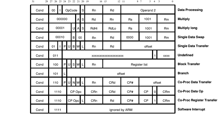
B|BL«cond» expression
MOV|MVN«cond»«S»Rd,op2
CMN|CMP|TEQ|TST«cond»«P»Rn,op2
ADC|ADD|AND|BIC|OR|ORR|RSB|RSC|SBC|SUB«cond»«S»Rd,Rn,op2
MRS«cond» Rd,psr
MSR«cond» psr,Rm
MSR«cond» psrf,Rm
MSR«cond» psrf,#expression
MUL«cond»«S» Rd,Rm,Rs
MLA«cond»«S» Rd,Rm,Rs,Rn
UMULL|SMULL|UMLAL|SMLAL«cond»«S» RdLo,RdHi,Rm,Rs
LDR|STR«cond»«B»«T» Rd,address
LDM|STM«cond»FD|ED|FA|EA|IA|IB|DA|DB Rn«!»,Rlist«^»
SWP«cond»«B» Rd,Rm,[Rn]
SWI«cond» expression
CDP«cond» CP#,operation,CRd,CRn,CRm«,info»
LDC|STC«cond»«L» CP#,CRd, address
MCR|MRC«cond» CP#,operation,Rd,CRn,CRm«,info»
| address | can be:
| ||||||||||
| «B» | means to transfer a byte, otherwise a word is transferred. | ||||||||||
| «cond» | is a two-character condition mnemonic; see the chapter entitled The condition field. | ||||||||||
| CP# | is the unique number of the required coprocessor, which must be a symbol defined via the CP directive. | ||||||||||
| CRd, CRn & CRm | are expressions evaluating to a valid coprocessor register number, which must be a symbol defined via the CN directive. | ||||||||||
| expression | for B and BL is a program-relative expression describing the branch destination, from which ObjAsm calculates the offset; for SWI, it is evaluated and placed in the comment field as a SWI number (which is ignored by ARM). | ||||||||||
| #expression | is an expression symbolising a 32 bit value. If #expression is used, ObjAsm will attempt to match the expression by generating a shifted immediate 8-bit field. If this is impossible, it will give an error. | ||||||||||
| info | where present is evaluated to a constant and placed in the CP field. | ||||||||||
| «L» | when present perform long transfer (N=1), otherwise perform short transfer (N=0). | ||||||||||
| op2 | may be any of the operands that the barrel shifter can produce.
The syntax is Rm«,shift» or #expression If #expression is used, ObjAsm will attempt to match the expression by generating a shifted immediate 8-bit field. If this is impossible, it will give an error. shift is shiftname Rs or shiftname #expression, or RRX (rotate right one bit with extend). shiftnames are: ASL, LSL, LSR, ASR, and ROR. (ASL is a synonym for LSL, and the two assemble to the same code.) See Shift types. | ||||||||||
| operation | is evaluated to a constant and placed in the CP Opc field. | ||||||||||
| «P» | means to take the result of a CMN, CMP, TEQ or TST operation, and move it to the bits of R15 that hold the PSR - even though the instruction has no destination register. Bits corresponding to the PC are masked out, as are (in User mode) the I, F, and mode bits. | ||||||||||
| psr | is CPSR, CPSR_all, SPSR or SPSR_all.
(CPSR and CPSR_all are synonyms, as are SPSR and SPSR_all.) | ||||||||||
| psrf | is CPSR_flg or SPSR_flg. The most significant four bits of Rm or #expression are written to the N, Z, C and V flags respectively. | ||||||||||
| Rd, RdLo, RdHi, Rm, Rn & Rs | are expressions evaluating to a valid ARM register number. | ||||||||||
| Rlist | is either a comma-separated list of registers and/or of register ranges indicated by hyphens, all enclosed in {} (e.g. {R0,R2-R7,R10}); or an expression evaluating to the 16 bit operand. | ||||||||||
| «S» | means to set the PSR's condition codes from the operation. ObjAsm forces this for CMN, CMP, TEQ and TST, provided the P flag is not specified. | ||||||||||
| «T» | means to set the W bit in a post-indexed instruction, forcing non-privileged mode for the transfer cycle. T is not allowed when a pre-indexed addressing mode is specified or implied. | ||||||||||
| «!» | if present sets the W bit to write-back the base register. | ||||||||||
| «^» | if present sets the S bit to load the PSR with the PC, or forces storing of user bank registers when in a non-user mode. |
For a detailed synopsis of the various instructions, see the following sections:
The above completes the description of all the basic ARM instructions. However, ObjAsm understands a number of other instructions, which it translates into appropriate basic ARM instructions.
In the case of an instruction such as
MOV R0,#VALUE
ObjAsm will evaluate the expression and produce a CPU instruction to load the value into the destination register. This may not in fact be the machine level instruction known as MOV, but the programmer need not be aware that an alternative instruction has been substituted. A common example is
MOV Rn,#-1
which the CPU cannot handle directly (as -1 is not a valid immediate constant). ObjAsm will accept this syntax, but will convert it and generate object code for
which results in Rn containing -1. Such conversions also takes place between the following pairs of instructions:
ADR«cond» register,expression
This produces an address in a register. ARM does not have an explicit 'calculate effective address' instruction, as this can generally be done using ADD, SUB, MOV or MVN. To ease the construction of such instructions, ObjAsm provides an ADR instruction.
The expression may be register-relative, program-relative or numeric:
will be produced, where register2 is the register to which the expression is relative.
will be produced.
will be produced.
In all three cases, an error will be generated if the immediate constant required is out of range.
If the program has a fixed origin (that is, if the ORG directive has been used), the distinction between program-relative and numeric values disappears. In this case, ObjAsm will first try to treat such a value as program-relative. If this fails, it will try to treat it as numeric. An error will only be generated if both attempts fail.
ADR«cond»L register,expression
This form of ADR is provided by ADRL and allows a wider collection of effective addresses to be produced. ADRL can be used in the same way as ADR, except that the allowed range of constants is any constant specified as an even rotation of a value less than &10000. Again program-relative, register relative and numeric forms exist. The result produced will always be two instructions, even if it could have been done in one. An error will be generated if the necessary immediate constants cannot be produced.
Literals are intended to enable the programmer to load immediate values into a register which might be out of range as MOV/MVN arguments.
ObjAsm will take certain actions with literals. It will:
Program-relative expressions and imported symbols are also valid literals. See the chapter entitled Organisational directives - END, ORG, LTORG and KEEP for further information.