
|
www.riscos.com Technical Support: |
The ARM has a general coprocessor interface. The first coprocessor available is one which performs floating point calculations to the IEEE standard. To ensure that programs using floating point arithmetic remain compatible with all Archimedes machines, a standard ARM floating point instruction set has been defined. This can be implemented invisibly to the customer program by one of several systems offering various speed performances at various costs. The current 'bundled' floating point system is the software only floating point emulator module. Floating point instructions may be incorporated into any assembler text, provided they are called from user mode. These instructions are recognised by the Assembler and converted into the correct coprocessor instructions.
Generally, programs do not need to know whether a coprocessor is fitted; the only effective difference is in the speed of execution. Note that there may be slight variations in accuracy between hardware and software - refer to the instructions supplied with the coprocessor for details of these variations.
The ARM IEEE floating point system has eight 'high precision' floating point registers, F0 to F7. The format in which numbers are stored in these registers is not specified. Floating point formats only become visible when a number is transferred to memory, using one of the formats described below.
There is also a floating point status register (FPSR) which, like the ARM's combined PC and PSR, holds all the necessary status and control information that an application is intended to be able to access. It holds flags which indicate various error conditions, such as overflow and division by zero. Each flag has a corresponding trap enable bit, which can be used to enable or disable a 'trap' associated with the error condition. Bits in the FPSR allow a client to distinguish between different implementations of the floating point system.
There may also be a floating point control register (FPCR); this is used to hold status and control information that an application is not intended to access. For example, there are privileged instructions to turn the floating point system on and off, to permit efficient context changes. Typically, hardware based systems have an FPCR, whereas software based ones do not.
Floating point systems may be built from software only, hardware only, or some combination of software and hardware. The following terminology will be used to differentiate between the various ARM floating point systems already in use:
| System name | System components |
|---|---|
| Old FPE | Versions of the floating point emulator up to (but not including) 4.00 |
| FPPC | Floating Point Protocol Convertor (interface chip between ARM and WE32206), WE32206 (AT&T Math Acceleration Unit chip), and support code |
| FPE 400 | Versions of the floating point emulator from 4.00 onwards |
| FPA | ARM Floating Point Accelerator chip, and support code |
The results look the same to the programmer. However, if clients are aware of which system is in use, they may be able to extract better performance. For example, compilers can be tuned to generate bunched FP instructions for the FPE and dispersed FP instructions for the FPA, which will improve overall performance
The old FPE has two different variants. Versions up to (but not including) 3.40 do not provide any hardware support, whereas versions 3.40 to 3.99 inclusive provide support for the FPPC hardware - if it is fitted. All versions of the FPE 400 provide support for the FPA hardware.
All basic floating point instructions operate as though the result were computed to infinite precision and then rounded to the length, and in the way, specified by the instruction. The rounding is selectable from:
The default is 'round to nearest'; in the event of a tie, this rounds to 'nearest even'. If any of the others are required they must be given in the instruction.
The working precision of the system is 80 bits, comprising a 64 bit mantissa, a 15 bit exponent and a sign bit. Specific instructions that work only with single precision operands may provide higher performance in some implementations, particularly the fully software based ones.
Like the ARM instructions, the floating point data processing operations refer to registers rather than memory locations. Values may be stored into ARM memory in one of five formats (only four of which are visible at any one time, since P and EP are mutually exclusive):
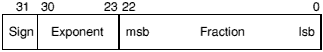
Single precision format
![[INFINITY]](../../symbols/entities/8734.png) .
.
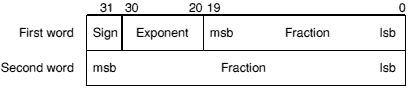
Double precision format
.
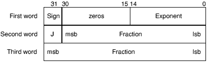
Double extended precision format
.
Other values are illegal and shall not be used (ie the exponent is in the range 1 to 32766 and J is 0; or the exponent is 32767, J is 1, and the fraction is 0).
The FPPC system stores the sign bit in bit 15 of the first word, rather than in bit 31.
Storing a floating point register in 'E' format is guaranteed to maintain precision when loaded back by the same floating point system in this format. Note that in the past the layout of E format has varied between floating point systems, so software should not have been written to depend on it being readable by other floating point systems. For example, no software should have been written which saves E format data to disc, to have then been potentially loaded into another system. In particular, E format in the FPPC system varies from all other systems in its positioning of the sign bit. However, for the FPA and the FPE 400, the E format is now defined to be a particular form of IEEE Double Extended Precision and will not vary in future.
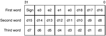
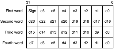
Packed decimal format
The sign nibble contains both the significand's sign (top bit) and the exponent's sign (next bit); the other two bits are zero.
d18 is the most significant digit of the significand d, and e3 of the exponent e. The significand has an assumed decimal point between d18 and d17, and is normalised so that for a normal number l  D18 9. The guaranteed ranges for d and e are 17 and 3 digits respectively; d0, d1 and e3 may always be zero in a particular system. (By comparison, an S format number has 9 digits of significand and a maximum exponent of 53; a D format number has 17 digits in the significand and a maximum exponent of 340.)
The result is undefined if any of the packed digits is hexadecimal A - F, save for a representation of ± or a NaN (see below).
Zero will always be output as +0, but either +0 or -0 may be input.
.
All other combinations are undefined.
Expanded packed decimal format
The sign nibble contains both the significand's sign (top bit) and the exponent's sign (next bit); the other two bits are zero.
d23 is the most significant digit of the significand d, and e6 of the exponent e. The significand has an assumed decimal point between d23 and d22, and is normalised so that for a normal number l D23 9. The guaranteed ranges for d and e are 21 and 4 digits respectively; d0, d1, d2, e4, e5 and e6 may always be zero in a particular system. (By comparison, an S format number has 9 digits of significand and a maximum exponent of 53; a D format number has 17 digits in the significand and a maximum exponent of 340.)
The result is undefined if any of the packed digits is hexadecimal A - F, save for a representation of ± or a NaN (see below).
Zero will always be output as +0, but either +0 or -0 may be input.
.
All other combinations are undefined.
This format is not available in the old FPE or the FPPC. You should only use it if you can guarantee that the floating point system you are using supports it.
There is a floating point status register (FPSR) which, like ARM's combined PC and PSR, has all the necessary status for the floating point system. The FPSR contains the IEEE flags but not the result flags - these are only available after floating point compare operations.
The FPSR consists of a system ID byte, an exception trap enable byte, a system control byte and a cumulative exception flags byte.
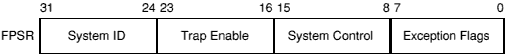
Floating point status register byte usage
The System ID byte allows a user or operating system to distinguish which floating point system is in use. The top bit (bit 31 of the FPSR) is set for hardware (ie fast) systems, and clear for software (ie slow) systems. Note that the System ID is read-only.
The following System IDs are currently defined:
| System | System ID |
|---|---|
| Old FPE | &00 |
| FPPC | &80 |
| FPE 400 | &01 |
| FPA | &81 |
Each bit of the exception trap enable byte corresponds to one type of floating point exception, which are described in the Cumulative Exception Flags Byte.
Exception trap enable byte
If a bit in the cumulative exception flags byte is set as a result of executing a floating point instruction, and the corresponding bit is also set in the exception trap enable byte, then that exception trap will be taken.
Currently, the reserved bits shall be written as zeros and will return 0 when read.
These control bits determine which features of the floating point system are in use.
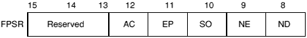
System control byte
By placing these control bits in the FPSR, their state will be preserved across context switches, allowing different processes to use different features if necessary. The following five control bits are defined for the FPA system and the FPE 400:
| ND | No Denormalised numbers |
| NE | NaN Exception |
| SO | Select synchronous Operation of FPA |
| EP | Use Expanded Packed decimal format |
| AC | Use Alternative definition for C flag on compare operations |
The old FPE and the FPPC system behave as if all these bits are clear.
Currently, the reserved bits shall be written as zeros and will return 0 when read. Note that all bits (including bits 8 - 12) are reserved on FPPC and early FPE systems.
If this bit is set, then the software will force all denormalised numbers to zero to prevent lengthy execution times when dealing with denormalised numbers. (Also known as abrupt underflow or flush to zero.) This mode is not IEEE compatible but may be required by some programs for performance reasons.
If this bit is clear, then denormalised numbers will be handled in the normal IEEE-conformant way.
If this bit is set, then an attempt to store a signalling NaN that involves a change of format will cause an exception (for full IEEE compatibility).
If this bit is clear, then an attempt to store a signalling NaN that involves a change of format will not cause an exception (for compatibility with programs designed to work with the old FPE).
If this bit is set, then all floating point instructions will execute synchronously and ARM will be made to busy-wait until the instruction has completed. This will allow the precise address of an instruction causing an exception to be reported, but at the expense of increased execution time.
If this bit is clear, then that class of floating point instructions that can execute asynchronously to ARM will do so. Exceptions that occur as a result of these instructions may be raised some time after the instruction has started, by which time the ARM may have executed a number of instructions following the one that has failed. In such cases the address of the instruction that caused the exception will be imprecise.
The state of this bit is ignored by software-only implementations, which always operate synchronously.
If this bit is set, then the expanded (four word) format will be used for Packed Decimal numbers. Use of this expanded format allows conversion from extended precision to packed decimal and back again to be carried out without loss of accuracy.
If this bit is clear, then the standard (three word) format is used for Packed Decimal numbers.
If this bit is set, the ARM C flag, after a compare, is interpreted as 'Greater Than or Equal or Unordered'. This interpretation allows more of the IEEE predicates to be tested by means of single ARM conditional instructions than is possible using the original interpretation of the C flag (as shown below).
If this bit is clear, the ARM C flag, after a compare, is interpreted as 'Greater Than or Equal'.
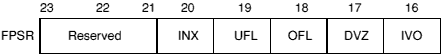
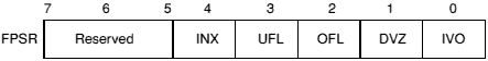
Cumulative exception flags byte
Whenever an exception condition arises, the appropriate cumulative exception flag in bits 0 to 4 will be set to 1. If the relevant trap enable bit is set, then an exception is also delivered to the user's program in a manner specific to the operating system. (Note that in the case of underflow, the state of the trap enable bit determines under which conditions the underflow flag will be set.) These flags can only be cleared by a WFS instruction.
Currently, the reserved bits shall be written as zeros and will return 0 when read.
The IVO flag is set when an operand is invalid for the operation to be performed. Invalid operations are:
P -
/
or y = 0
(REM is the 'remainder after floating point division' operator.)
![[ROOT]](../../symbols/entities/8730.png) (-0) = -0)
or a NaN operand make it impossible
(-0) = -0)
or a NaN operand make it impossible
If overflow makes a conversion to integer impossible, then the largest positive or negative integer is produced (depending on the sign of the operand) and IVO is signalled
0
0
0 and second operand is 0.
The DVZ flag is set if the divisor is zero and the dividend a finite, non-zero number. A correctly signed infinity is returned if the trap is disabled.
The flag is also set for LOG(0) and for LGN(0). Negative infinity is returned if the trap is disabled.
The OFL flag is set whenever the destination format's largest number is exceeded in magnitude by what the rounded result would have been were the exponent range unbounded. As overflow is detected after rounding a result, whether overflow occurs or not after some operations depends on the rounding mode.
If the trap is disabled either a correctly signed infinity is returned, or the format's largest finite number. This depends on the rounding mode and floating point system used.
Two correlated events contribute to underflow:
The UFL flag is set in different ways depending on the value of the UFL trap enable bit. If the trap is enabled, then the UFL flag is set when tininess is detected regardless of loss of accuracy. If the trap is disabled, then the UFL flag is set when both tininess and loss of accuracy are detected (in which case the INX flag is also set); otherwise a correctly signed zero is returned.
As underflow is detected after rounding a result, whether underflow occurs or not after some operations depends on the rounding mode.
The INX flag is set if the rounded result of an operation is not exact (different from the value computable with infinite precision), or overflow has occurred while the OFL trap was disabled, or underflow has occurred while the UFL trap was disabled. OFL or UFL traps take precedence over INX.
The INX flag is also set when computing SIN or COS, with the exceptions of SIN(0) and COS(1).
The old FPE and the FPPC system may differ in their handling of the INX flag. Because of this inconsistency we recommend that you do not enable the INX trap.
The Floating Point Control register (FPCR) may only be present in some implementations: it is there to control the hardware in an implementation-specific manner, for example to disable the floating point system. The user mode of the ARM is not permitted to use this register (since the right is reserved to alter it between implementations) and the WFC and RFC instructions will trap if tried in user mode.
You are unlikely to need to access the FPCR; this information is principally given for completeness.
The FPCR bit allocation in the FPPC system is as shown below:
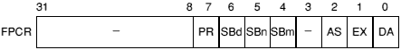
FPCR bit allocation in the FPPC system
| Bit | Meaning | |
|---|---|---|
| 31-8 | Reserved - always read as zero | |
| 7 | PR | Last RMF instruction produced a partial remainder |
| 6 | SBd | Use Supervisor Register Bank 'd' |
| 5 | SBn | Use Supervisor Register Bank 'n' |
| 4 | SBm | Use Supervisor Register Bank 'm' |
| 3 | Reserved - always read as zero | |
| 2 | AS | Last WE32206 exception was asynchronous |
| 1 | EX | Floating point exception has occurred |
| 0 | DA | Disable |
Reserved bits are ignored during write operations (but should be zero for future compatibility.) The reserved bits will return zero when read.
In the FPA, the FPCR will also be used to return status information required by the support code when an instruction is bounced. You should not alter the register unless you really know what you're doing. Note that the register will be read sensitive; even reading the register may change its value, with disastrous consequences.
The FPCR bit allocation in the FPA system is provisionally as follows:
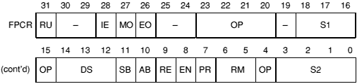
FPCR bit allocation in the FPA system
| Bit | Meaning | |
|---|---|---|
| 31 | RU | Rounded Up Bit |
| 30 | Reserved | |
| 29 | Reserved | |
| 28 | IE | Inexact bit |
| 27 | MO | Mantissa overflow |
| 26 | EO | Exponent overflow |
| 25, 24 | Reserved | |
| 23-20 | OP | AU operation code |
| 19 | PR | AU precision |
| 18-16 | S1 | AU source register 1 |
| 15 | OP | AU operation code |
| 14-12 | DS | AU destination register |
| 11 | SB | Synchronous bounce: decode (R14) to get opcode |
| 10 | AB | Asynchronous bounce: opcode supplied in rest of word |
| 9 | RE | Rounding Exception: Asynchronous bounce occurred during rounding stage and destination register was written |
| 8 | EN | Enable FPA (default is off) |
| 7 | PR | AU precision |
| 6, 5 | RM | AU rounding mode |
| 4 | OP | AU operation code |
| 3-0 | S2 | AU source register 2 (bit 3 set denotes a constant) |
Note that the SB and AB bits are cleared on a read of the FPCR. Only the EN bit is writable. All other bits shall be set to zero on a write.
The precision letter determines the format used to store the number in memory, as follows:
| Letter | Precision | Memory usage |
|---|---|---|
| S | Single | 1 word |
| D | Double | 2 words |
| E | Extended | 3 words |
| P | Packed BCD | 3 words |
| EP | Extended Packed BCD | 4 words |
For details of these formats see the chapter entitled Floating point number formats.
A floating point number recognised by the assemblers consists of an optional sign, followed by an optional mantissa part followed by an optional exponent part. One or other of the mantissa part and the exponent part must be present. The mantissa part consists of a sequence of zero or more decimal digits, followed by an optional decimal point followed by a sequence of zero or more decimal digits. If present, the mantissa must contain a non-zero number of digits overall. The exponent part begins with 'e' or 'E', followed by an optional sign, followed by a sequence of one or more decimal digits.
Examples are:
1
0.2
5E9
E-2
-.7
+31.415926539E-1
The value generated represents the mantissa multiplied by ten to the power of the exponent, where the mantissa is taken to be one if missing, and the exponent is taken to be zero if missing. All reading is done to double precision, and is then rounded to single precision as required. The required precision is determined by the context as shown in the sections Floating point store loading directives and Floating point literals.
If you know that your code should not use floating point instructions and want to ensure that you don't accidentally include them, you can use the NOFP directive. It must occur before any floating point instructions or directives.
Syntax: NOFP
The directive FN is used to assign a floating point register number 0-7 to a symbol.
Syntax: label FN numeric expression
Floating point register numbers are taken to be constants when included in arbitrary expression, but only floating point register names are valid when a floating point register is required.
Directives DCFS and DCFD are provided to load store with respectively single and double precision floating point numbers. Single precision floating point numbers occupy one word of store, double precision floating point numbers occupy two words, but are not constrained to be double word aligned.
Syntax: label DCFx floating point number«,floating point number»
where the syntax of floating point numbers is defined in the section Floating point number input above.
?label will have the value of the number of bytes of code generated by its defining line in a way analogous to DCD.
op«condition»prec Fd,addr
Load (LDF) or store (STF) the high precision value from or to memory, using one of the five memory formats. On store, the value is rounded using the 'round to nearest' rounding method to the destination precision, or is precise if the destination has sufficient precision. Thus other rounding methods may be used by having previously applied some suitable floating point data operation; this does not compromise the requirement of 'rounding once only', since the store operation introduces no additional rounding error.
The offset is in words from the address given by the ARM base register, and is in the range -1020 to +1020. In pre-indexed mode you must explicitly specify writeback to add the offset to the base register; but in post-indexed mode the assembler forces writeback for you, as without write back post-indexing is meaningless.
You should not use R15 as the base register if writeback will take place.
Examples:
LDFS    F0,[R0]         ; load F0 from address held in R0
                        ; (single precision)
STFP    F1,[R2]         ; store number held in F1 at R2
                        ; as a packed decimal number
LDFS and LDFD can be given literal values instead of a register relative address, and the Assembler will automatically place the required value in the next available literal pool. In the case of LDFS a single precision value is placed, in the case of LDFD a double precision value is placed. Because the allowed offset range within a LDFS or LDFD instruction is less than that for a LDR instruction (-1020 to +1020 instead of -4095 to +4095), it may be necessary to code LTORG directives more frequently if floating point literals are being used than would otherwise be necessary.
The LFM and SFM multiple data transfer instructions are supported by the assemblers, but are not provided by the FPPC system, or by some versions of the old FPE:
Attempting to execute these instructions on systems that do not provide them will cause undefined instruction traps, so you should only use these instructions in software intended for machines you are confident are using an appropriate version of the old FPE, or the FPE 400, or the FPA system.
The LFM and SFM instructions allow between 1 and 4 floating point registers to be transferred from or to memory in a single operation; such a transfer otherwise requires several LDF or STF operations. The multiple transfers are therefore useful for efficient stacking on procedure entry/exit and context switching. These new instructions are the preferred way to preserve exactly register contents within a program.
The values transferred to memory by SFM occupy three words for each register, but the data format used is not defined, and may vary between floating point systems. The only legal operation that can be performed on this data is to load it back into floating point registers using the LFM instruction. The data stored in memory by an SFM instruction should not be used or modified by any user process.
The registers transferred by a LFM or SFM instruction are specified by a base floating point register and the number of registers to be transferred. This means that a register set transferred has to have adjacent register numbers, unlike the unconstrained set of ARM registers that can be loaded or saved using LDM and STM. Floating point registers are transferred in ascending order, register numbers wrapping round from 7 to 0: eg transferring three registers with F6 as the base register results in registers F6, F7 then F0 being transferred.
The assembler supports two alternative forms of syntax, intended for general use or just stack manipulation:
op«condition» Fd,count,addr
op«condition»stacktype Fd,count,[Rn]«!»
The offset (only relevant for the first, general, syntax above) is in words from the address given by the ARM base register, and is in the range -1020 to +1020. In pre-indexed mode you must explicitly specify writeback to add the offset to the base register; but in post-indexed mode the assembler forces writeback for you, as without write back post-indexing is meaningless.
You should not use R15 as the base register if writeback will take place.
Examples:
SFMNE   F6,4,[R0]       ; if NE is true, transfer F6, F7,
                        ; F0 and F1 to the address
                        ; contained in R0

LFMFD   F4,2,[R13]!     ; load F4 and F5 from FD stack -
LFM     F4,2,[R13],#24  ; equivalent to same instruction
                        ; in general syntax
FLT«condition»prec«round» Fn,Rd
FLT«condition»prec«round» Fn,#value
FIX«condition»«round» Rd,Fn
WFS«condition» Rd
RFS«condition» Rd
WFC«condition» Rd
RFC«condition» Rd
| «round» | is the optional rounding mode: P, M or Z; see below. |
| Rd | is an ARM register symbol. |
| Fn | is a floating point register symbol. |
The value may be of the following: 0, 1, 2, 3, 4, 5, 10, 0.5. Note that these values must be written precisely as shown above, for instance '0.5' is correct but '.5' is not.
| FLT | Integer to Floating Point | Fn := Rd | |
| FIX | Floating point to integer | Rd := Fm | |
| WFS | Write Floating Point Status | FPSR := Rd | |
| RFS | Read Floating Point Status | Rd := FPSR | |
| WFC | Write Floating Point Control | FPC := Rd | Supervisor Only |
| RFC | Read Floating Point Control | Rd := FPC | Supervisor Only |
| Mode | Letter |
|---|---|
| Nearest | (no letter required) |
| Plus infinity | P |
| Minus infinity | M |
| Zero | Z |
The formats of these instructions are:
binop«condition»prec«round» Fd,Fn,Fm
binop«condition»prec«round» Fd,Fn#value
unop«condition»prec«round» Fd,Fm
unop«condition»prec«round» Fd,#value
| binop | is one of the binary operations listed below |
| unop | is one of the unary operations listed below |
| Fd | is the FPU destination register |
| Fn | is the FPU source register (binops only) |
| Fm | is the FPU source register |
| #value | is a constant, as an alternative to Fm. It must be 0, 1, 2, 3, 4, 5, 10 or 0.5, as above. |
The binops are:
| ADF | Add | Fd := Fn + Fm |
| MUF | Multiply | Fd := Fn × Fm |
| SUF | Subtract | Fd := Fn - Fm |
| RSF | Reverse Subtract | Fd := Fm - Fn |
| DVF | Divide | Fd := Fn / Fm |
| RDF | Reverse Divide | Fd := Fm / Fn |
| POW | Power | Fd := Fn to the power of Fm |
| RPW | Reverse Power | Fd := Fm to the power of Fn |
| RMF | Remainder | Fd := remainder of Fn / Fm (Fd := Fn - integer value of (Fn / Fm) × Fm) |
| FML | Fast Multiply | Fd := Fn × Fm |
| FDV | Fast Divide | Fd := Fn / Fm |
| FRD | Fast Reverse Divide | Fd := Fm / Fn |
| POL | Polar angle | Fd := polar angle of Fn, Fm |
The unops are:
| MVF | Move | Fd := Fm |
| MNF | Move Negated | Fd := -Fm |
| ABS | Absolute value | Fd := ABS (Fm) |
| RND | Round to integral value | Fd := integer value of Fm |
| SQT | Square root | Fd := square root of Fm |
| LOG | Logarithm to base 10 | Fd := log Fm |
| LGN | Logarithm to base e | Fd := ln Fm |
| EXP | Exponent | Fd := e to the power of Fm |
| SIN | Sine | Fd := sine of Fm |
| COS | Cosine | Fd := cosine of Fm |
| TAN | Tangent | Fd := tangent of Fm |
| ASN | Arc Sine | Fd := arcsine of Fm |
| ACS | Arc Cosine | Fd := arccosine of Fm |
| ATN | Arc Tangent | Fd := arctangent of Fm |
| URD | Unnormalised Round | Fd := integer value of Fm (may be abnormal) |
| NRM | Normalise | Fd := normalised form of Fm |
Note that wherever Fm is mentioned, one of the floating point constants 0, 1, 2, 3, 4, 5, 10, or 0.5 can be used instead.
FML, FRD and FDV are only defined to work with single precision operands. These 'fast' instructions are likely to be faster than the equivalent MUF, DVF and RDF instructions, but this is not necessarily so for any particular implementation.
Rounding is done only at the last stage of a SIN, COS etc - the calculations to compute the value are done with 'round to nearest' using the full working precision.
The URD and NRM operations are only supported by the FPA and the FPE 400.
op«condition»prec«round» Fm,Fn
op is one of the following:
| «condition» | an ARM condition. |
| prec | a precision letter |
| «round» | an optional rounding mode: P, M or Z |
| Fm | A floating point register symbol. |
| Fn | A floating point register symbol. |
Compares are provided with and without the exception that could arise if the numbers are unordered (ie one or both of them is not-a-number). To comply with IEEE 754, the CMF instruction should be used to test for equality (ie when a BEQ or BNE is used afterwards) or to test for unorderedness (in the V flag). The CMFE instruction should be used for all other tests (BGT, BGE, BLT, BLE afterwards).
When the AC bit in the FPSR is clear, the ARM flags N, Z, C, V refer to the following after compares:
| N | Less than | ie Fn less than Fm (or -Fm) |
| Z | Equal | |
| C | Greater than or equal | ie Fn greater than or equal to Fm (or -Fm) |
| V | Unordered |
Note that when two numbers are not equal, N and C are not necessarily opposites. If the result is unordered they will both be clear.
When the AC bit in the FPSR is set, the ARM flags N, Z, C, V refer to the following after compares:
| N | Less than |
| Z | Equal |
| C | Greater than or equal or unordered |
| V | Unordered |