
|
www.riscos.com Technical Support: |
The ARM (Advanced Risc Machine) is a general purpose 32 bit single chip microprocessor. The architecture is based on Reduced Instruction Set Computer (RISC) principles, and the instruction set and related decode mechanism are greatly simplified compared with microprogrammed Complex Instruction Set Computers. This simplification results in a high instruction throughput and a good real-time interrupt response from a small and cost-effective chip.
The ARM2 and ARM3 have a 32 bit data bus and a 26 bit address bus. On later versions of the ARM, both the data bus and the address bus are a full 32 bits wide.
All instructions fit into one 32 bit word, and they can all be made conditional.
The ARM instruction set comprises ten basic classes of instruction:
Two of these make use of the on-chip arithmetic logic unit (ALU), barrel shifter and multiplier to perform high-speed operations on the data in the 32 bit registers. Three instruction classes control the transfer of data between main memory and the register bank, one optimised for flexibility of addressing, another for rapid context switching, and the third for swapping data. Two instruction classes control the flow and privilege level of execution. The remaining three classes are dedicated to the control of external coprocessors, which allow the functionality of the instruction set to be extended off-chip in an open and uniform way.
The ARM instruction set has proved to be a good target for compilers of many different high-level languages. Where required for critical code segments, assembly code programming is also straightforward, unlike some RISC processors which depend on sophisticated compiler technology to manage complicated instruction interdependencies.
The instruction set is detailed in the CPU instruction set.
Pipelining is employed so that all parts of the processing and memory systems can operate continuously.
The ARM uses a 3-stage instruction pipeline. This allows it to execute one instruction, and at the same time both to decode the following instruction, and to fetch the one after that from memory.
The memory interface has been designed to allow the performance potential to be realised without incurring high costs in the memory system. Speed critical control signals are pipelined to allow system control functions to be implemented in standard low-power logic, and these control signals facilitate the exploitation of the fast local access modes offered by industry standard dynamic random access memories (DRAMs).
The processor can access two types of data:
where words must be aligned to four byte boundaries.
Instructions are fetched as words, and so must be aligned to four byte boundaries. Data operations (eg ADD) are only performed on word quantities. Load and store operations can transfer either bytes or words, and can put a full 26 or 32 bit address (depending on the processor variant) - with bits 0 and 1 set as required - on to the address bus.
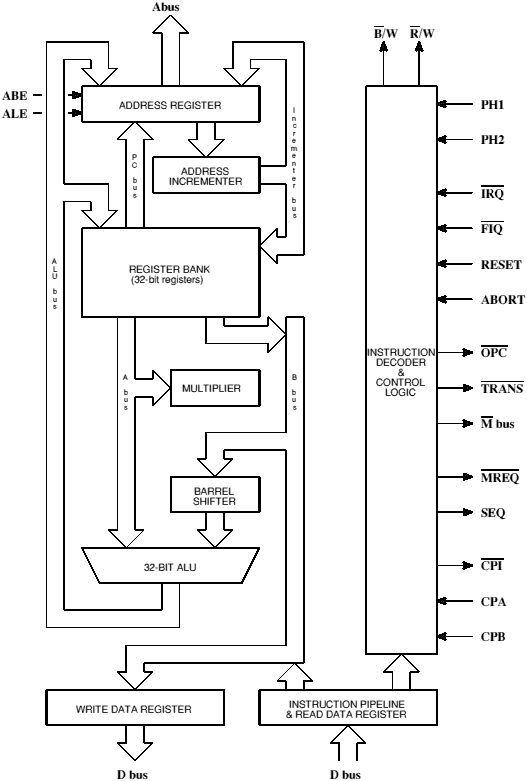
ARM Core block diagram
This section describes the architecture of the ARM2 and ARM3 series, which only supported a 26 bit address space. However, as we shall see in the 32 bit architecture, much of this is also relevant to later series of ARM when used so as to provide backward-compatibility with the earlier 26 bit processors.
These older ARM series support four modes of operation:
Mode changes may be made under software control or may be brought about by external interrupts or exception processing. Most application programs will execute in User mode. The other modes, known as privileged modes, will be entered to service interrupts or exceptions or to access protected resources.
The ARM has a number of 32 bit registers, 16 of which are visible to the programmer at any time. This subset depends on the processor mode:
The IRQ and SVC modes have two private registers mapped to R13 and R14 (R13_irq and R14_irq, and R13_svc and R14_svc respectively).
The FIQ mode has more private registers so that FIQ code - which needs to respond quickly - is less likely to need to use any of the shared registers, and so will be spared the overhead of saving them to a stack. Its seven private registers are mapped to R8-R14 (R8_fiq-R14_fiq).
The register bank organisation is shown in the 26 bit register organisation below:
| User mode | SVC mode | IRQ mode | FIQ mode |
|---|---|---|---|
| R0 | |||
| R1 | |||
| R2 | |||
| R3 | |||
| R4 | |||
| R5 | |||
| R6 | |||
| R7 | |||
| R8 | R8_fiq | ||
| R9 | R9_fiq | ||
| R10 | R10_fiq | ||
| R11 | R11_fiq | ||
| R12 | R12_fiq | ||
| R13 | R13_svc | R13_irq | R13_fiq |
| R14 | R14_svc | R14_irq | R14_fiq |
| R15 (PC/PSR) | |||
All registers are general purpose and may be used to hold data or address values, except for R15 and R14:
R13 is also often used for a special purpose:
The private copies of R13 and R14 allow each mode to have a private stack pointer and link register. SVC and IRQ mode programs are expected to save the User state on their respective stacks and then use the User registers, remembering to restore the User state before returning.
R15 contains 24 bits of program counter (PC) and 8 bits of processor status register (PSR).
The program counter (PC) is 24 bits wide and counts to &FFFFFF. However, two low-order bits (both zeros) are appended to the PC value and a 26 bit value is put on the address bus, thus quadrupling the total count to &3FFFFFC. The memory capacity of the ARM processor is 64 Mbytes, or 16 Mwords. The PC is always a multiple of four because of the two appended zeros, and so it follows that instructions must be aligned to four byte boundaries.
Special bits in some instructions allow the PC and PSR to be treated together, or separately, as required. The allocation of the bits within the register R15 is shown in the The Program Counter (PC) and Process Status Register (PSR) below.
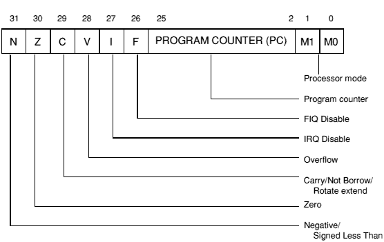
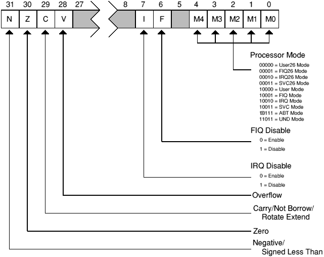
The mnemonics for the four condition flags are derived as follows:
| N | Negative flag |
| Z | Zero flag |
| C | Carry flag |
| V | Overflow flag |
The condition flags may be altered in any mode. The I, F, and Mode flags can only be changed directly in privileged modes; they are also modified when exceptions occur or SWI instructions are executed.
R14 is used as the subroutine Link register, and receives a copy of the return PC and PSR when a Branch and Link instruction is executed (see Branch, Branch with Link (B, BL)). It may be treated as a general purpose register at all other times. Similarly, R14_svc, R14_irq and R14_fiq are used to hold the return values of R15 when interrupts and exceptions arise, or when Branch and Link instructions are executed within supervisor or interrupt routines.
In the Assembler, the suffix P added to a CMN, CMP, TEQ or TST instruction causes the instruction to change the PSR directly. Such instructions can be used to change the ARM's mode, for example:
TEQP R15,#2  changes to IRQ mode
TEQP R15,#0  changes to user mode.
The action is to Exclusive OR the first operand with a supplied immediate field. R15 is the first operand. Whenever R15 is presented to the processor as the first operand, 24 bits are presented; the PSR bits are supplied as zero. The TEQ causes the immediate field value to be written into the register, and the P causes the PSR bits (now altered by the immediate field value) to be written back into R15. Since two of the PSR bits are the mode control bits, the processor assumes its new mode.
As the mode control bits cannot be set in User mode, this technique will not work in User mode. There are, however, two ways to pass from User mode to other modes:
Note: For more details of instructions executed immediately following a mode change see the sections Forcing transfer of the user bank and Using R15 as the destination.
The ARM architecture changed significantly with the introduction of the ARM6 series. This section describes the differences in behaviour of more recent ARM processors.
The most notable change made in the ARM6 series was to extend the program counter to a full 32 bits. As a result:
A further change was the addition of extra privileged processor modes, allowed by the PSR now having a full 32 bits to use. These modes are used to handle Undefined instruction and Abort exceptions. Consequently:
The availability of these features in the ARM6 series (and other later compatible chips) is set by one of several on-chip control registers. One of three processor configurations can be selected:
This configuration is set at reset on all current ARM6 and 7 series processors.
When configured for a 32 bit program and data space, the ARM6 and ARM7 series support ten overlapping processor modes of operation:
The distinction between processor modes and configurations is important, and will be rigidly adhered to in the rest of this manual.
When in a 26 bit processor mode, the programmer's model reverts to that of earlier 26 bit ARM processors. The behaviour is the same as that of the ARM2aS macrocell with the following alterations:
In other configurations the OS may still simulate the behaviour of address exception, using external logic such as a memory management unit to generate an abort if the 64Mbyte range is exceeded, and converting that abort into an 'address exception trap' for the application.
In all other respects, when operating in a 26 bit mode the ARM behaves as like a 26 bit ARM. (See the chapter entitled 26 bit architecture.) The relevant bits of the CPSR appear to be incorporated back into R15 to form the PC/PSR with the I and F bits in bits 27 and 26. The instruction set behaves like that of the ARM2aS macrocell, with the addition of the MRS and MSR instructions.
For details, see the chapter entitled RISC OS processor configuration and modes.
The registers available in the ARM6 and ARM7 series are:
| User and User26 mode | SVC and SVC26 mode | IRQ and IRQ26 mode | ABT mode | UND mode | FIQ and FIQ26 mode |
|---|---|---|---|---|---|
| R0 | |||||
| R1 | |||||
| R2 | |||||
| R3 | |||||
| R4 | |||||
| R5 | |||||
| R6 | |||||
| R7 | |||||
| R8 | R8_fiq | ||||
| R9 | R9_fiq | ||||
| R10 | R10_fiq | ||||
| R11 | R11_fiq | ||||
| R12 | R12_fiq | ||||
| R13 | R13_svc | R13_irq | R13_abt | R13_und | R13_fiq |
| R14 | R14_svc | R14_irq | R14_abt | R14_und | R14_fiq |
| R15 (PC) | |||||
| CPSR | |||||
| SPSR_svc | SPSR_irq | SPSR_abt | SPSR_und | SPSR_fiq | |
32 bit register organisation
These are similar to those available in the ARM2 and ARM3 series registers. The key differences are:
The allocation of the bits within the CPSR (and the SPSR registers to which it is saved) is shown in the The Current Process Status Register (CPSR) below.
This last section of the chapter is mainly of interest to operating systems programmers - for example when constructing relocatable modules. If you are writing applications, you can skip forward to the ARM assembly language.
This section describes the general behaviour of the ARM, rather than its behaviour under RISC OS. For details specific to RISC OS you must also see the chapter entitled Exception handling.
Exceptions arise whenever there is a need for the normal flow of program execution to be broken, so that (for instance) the processor can be diverted to handle an interrupt from a peripheral. The processor state just prior to handling the exception must be preserved so that the original program can be resumed when the exception routine has completed. Many exceptions may arise at the same time.
ARM handles exceptions by making use of the banked registers to save state. The old PC and PSR are copied, in a 26 bit configuration to the appropriate R14, or in a 32 bit configuration to the appropriate R14 and SPSR. The PC and processor mode bits are forced to a value which depends on the exception. Interrupt disable flags are set where required to prevent otherwise unmanageable nestings of exceptions. In the case of a re-entrant interrupt handler, R14 should be saved onto a stack in main memory before re-enabling the interrupt. When multiple exceptions arise simultaneously a fixed priority determines the order in which they are handled.
The FIQ (Fast Interrupt reQuest) exception is externally generated by taking the FIQ pin LOW. This input can accept asynchronous transitions, and is delayed by one clock cycle for synchronisation before it can affect the processor execution flow. It is designed to support a data transfer or channel process, and has sufficient private registers to remove the need for register saving in such applications, so that the overhead of context switching is minimised.
The FIQ exception may be disabled by setting the F flag in the PSR (but note that this is not possible from User mode). If the F flag is clear ARM checks for a LOW level on the output of the FIQ synchroniser at the end of each instruction.
When ARM is successfully FIQed it will:
To return normally from FIQ use:
SUBS PC,R14_fiq,#4
This will resume execution of the interrupted code sequence, and restore the original mode and interrupt enable state.
The IRQ (Interrupt ReQuest) exception is a normal interrupt caused by a LOW level on the IRQ pin. This input can accept asynchronous transitions, and is delayed by one clock cycle for synchronisation before it can affect processor execution. It has a lower priority than FIQ, and is masked out when a FIQ sequence is entered. Its effect may be masked out at any time by setting the I bit in the PC (but note that this is not possible from user mode). If the I flag is clear ARM checks for a LOW level on the output of the IRQ synchroniser at the end of each instruction.
When ARM is successfully IRQed it will:
To return normally from IRQ use:
SUBS PC,R14_irq,#4
This will restore the original processor state and thereby re-enable IRQ.
On a 32 bit configuration processor, address exceptions are never generated, and you may therefore ignore this section for such processors.
On a 26 bit configuration processor, an address exception arises whenever a data transfer is attempted with a calculated address above &3FFFFFF. The ARM address bus is 26 bits wide, but an address calculation has a 32 bit result. If this result has a logic '1' in any of the top 6 bits it is assumed that the address overflow is an error, and the address exception trap is taken.
Note that a branch cannot cause an address exception, and a block data transfer instruction which starts in the legal area but increments into the illegal area will not trap (it wraps round to address 0 instead). The check is performed only on the address of the first word to be transferred.
When an address exception is seen ARM will:
Normally an address exception is caused by erroneous code, and it is inappropriate to resume execution. If a return is required from this trap, use SUBS PC,R14_svc,#4. This will return to the instruction after the one causing the trap.
The Abort signal comes from an external Memory Management system, and indicates that the current memory access cannot be completed. For instance, in a virtual memory system the data corresponding to the current address may have been moved out of memory onto a disc, and considerable processor activity may be required to recover the data before the access can be performed successfully. ARM checks for an Abort at the end of the first phase of each bus cycle. When successfully Aborted ARM will respond in one of three ways.
If abort is signalled during an instruction prefetch (a Prefetch abort), the prefetched instruction is marked as invalid; when it comes to execution, it is reinterpreted as below. (If the instruction is not executed, for example as a result of a branch being taken while it is in the pipeline, the abort will have no effect.)
Then ARM will:
To continue after a Prefetch abort use SUBS PC,R14,#4 (where R14 is R14_svc or R14_abt depending on the processor configuration). The ARM will then re-execute the aborting instruction, so you should ensure that you have removed the cause of the original abort.
If the abort command occurs during a data access (a Data Abort), the action depends on the instruction type.
Then ARM will:
To continue after a data abort, remove the cause of the abort, then reverse any auto-indexing that the original instruction may have done, then return to the original instruction with SUBS PC,R14,#8 (where R14 is R14_svc or R14_abt depending on the processor configuration).
The ARM ignores aborts signalled during internal cycles.
The abort mechanism allows a 'demand paged virtual memory system' to be implemented when a suitable memory management unit (such as MEMC) is available. The processor is allowed to generate arbitrary addresses, and when the data at an address is unavailable the memory manager signals an abort. The processor traps into system software which must work out the cause of the abort, make the requested data available, and retry the aborted instruction. The application program needs no knowledge of the amount of memory available to it, nor is its state in any way affected by the abort.
The software interrupt instruction is used for getting into supervisor mode, usually to request a particular supervisor function. ARM will:
To return from a SWI, use MOVS PC,R14_svc. This returns to the instruction following the SWI.
When ARM executes a coprocessor instruction or an undefined instruction, it offers it to any coprocessors which may be present. If a coprocessor can perform this instruction but is busy at that moment, ARM will wait until the coprocessor is ready. If no coprocessor can handle the instruction ARM will take the undefined instruction trap.
When the undefined instruction trap is taken ARM will:
The undefined instruction trap may be used for software emulation of a coprocessor in a system which does not have the coprocessor hardware; or for general purpose instruction set extension by software emulation (the floating point instruction set is implemented in software this way).
To return from this trap (after performing a suitable emulation of the required function), use MOVS PC,R14 (where R14 is R14_svc or R14_und depending on the processor configuration). This will return to the instruction following the undefined instruction.
ARM can be reset by pulling its RESET pin HIGH. If this happens, ARM will stop the currently executing instruction and start executing no-ops. When RESET goes LOW again, it will:
The first eight words of store normally contain branch instructions pointing to the relevant routines. The FIQ routine may reside at &000001C onwards, and thereby avoid the need for (and execution time of) a branch instruction.
| Address | Definition |
|---|---|
| &0000000 | Reset |
| &0000004 | Undefined instruction |
| &0000008 | Software interrupt |
| &000000C | Abort (prefetch) |
| &0000010 | Abort (data) |
| &0000014 | Address exception |
| &0000018 | IRQ |
| &000001C | FIQ |
When multiple exceptions arise at the same time, a fixed priority system determines the order in which they will be handled:
Note that not all exceptions can occur at once. Address exception and data abort are mutually exclusive, since if an address is illegal the ARM will ignore the ABORT input. Undefined instruction and software interrupt are also mutually exclusive since they each correspond to particular (non-overlapping) decodings of the current instruction.
If an address exception or data abort occurs at the same time as a FIQ, and FIQs are enabled (ie the F flag in the PSR is clear), ARM will enter the address exception or data abort handler and then immediately proceed to the FIQ vector. A normal return from FIQ will cause the address exception or data abort handler to resume execution. Placing address exception and data abort at a higher priority than FIQ is necessary to ensure that the transfer error does not escape detection, but the time for this exception entry should be added to worst case FIQ latency calculations.
The worst case latency for FIQ, assuming that it is enabled, consists of the longest time the request can take to pass through the synchroniser, plus the time for the longest instruction (typically load multiple registers) to complete, plus the time for address exception or data abort entry, plus the time for FIQ entry. At the end of this time ARM will be executing the instruction at 1CH.
The maximum IRQ latency calculation is similar, but must allow for the fact that FIQ has higher priority and could delay entry into the IRQ handling routine for an arbitrary length of time.
The minimum latency for FIQ or IRQ consists of the shortest time the request can take through the synchroniser, plus the time for FIQ or IRQ entry.
The above times can vary considerably between different versions of the ARM, and obviously also depend on clock speeds. For more information you should see the relevant datasheets.