|
Editing objects
When you designed your object in Draw, you constructed it out of paths; you can edit these paths to fine-tune your objects shape. This is done using Path edit mode and the Path edit menu.
Path edit mode
To start editing your object, enter Path edit mode in one of the following ways:
- From Enter mode (when one of the top eight icons is highlighted), click ADJUST on the object you wish to edit.
- From Select mode (when the arrow icon is highlighted), first select an object, then choose Edit from the Select submenu or press Ctrl-E.
The end points and control points of the path are shown on the screen. To move any of the points, position the pointer over the point and press ADJUST . Drag the point to where you want it and release ADJUST.
When you have finished editing your object, leave Path edit mode by clicking SELECT or ADJUST when the mouse position is not over a path.
Editing curves
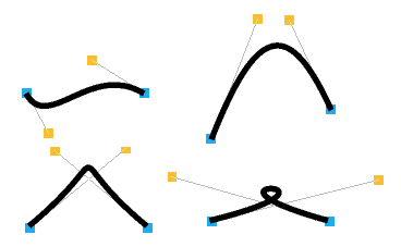
Curves in a path object are defined by two end points and two control points When you are drawing or editing a path, the control points are shown connected to the end points by straight lines. The shape of a curve is determined as follows;
- The direction of the curve at the end point lies along the straight line connecting the end point to the control point (ie this line is a tangent to the curve).
- The degree to which the curve moves away from this straight line depends on the distance of the control point from the end point: the nearer together they are. the sooner the curve turns away.
By moving the control points, you can produce many different shapes of curve. Some examples are shown below. In each case the thick line shows the path itself, and the control points (shown as yellow squares) are joined to the corresponding end points by thin lines,
If you hold down Shift while you drag a control point, the corresponding control point in the next curve is also moved to keep the angle of join constant.

Editing text lines
When typing in text, you can only delete text and type new text in if you are still on the same line. As soon as you press Return the line is frozen. To edit a text line once it is frozen use the following procedure:
- From Select mode (when the arrow icon is highlighted) first select the text line by clicking over it.
- Use the Selection menu to move to the Edit option and slide off this to display the Text box.
- Change the text in the text box and when you have finished press Return or click on Set and the text is changed.
Alternatively you can Select the text you want to edit and press Ctrl-E. The Text dialogue will appear and you can modify the text and then either click on Set or press Return to alter the text in the Draw window.

Text areas and bitmap images (sprites, JPEGs etc.) cannot be edited within Draw. Text areas should be exported to Edit and edited. Paint images (sprites and JPEGS) should be exported to Paint and edited.
The Path edit submenu
To view the Path edit menu. first enter Path edit mode as explained above. If the path you want to edit is under another object's path, clicking ADJUST over that path will find the next deeper path in the diagram if there is one. This is similar to tunnelling through objects in a selection.
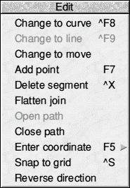
Select part of a path by clicking ADJUST on an end point or a control point of the path. The selected line segment is highlighted. (Note that if you select the first point of the path, there is no highlighting). You can now click MENU to show the list of Path edit actions.

Change to curve turns the selected part of the path into a curved line segment. You can use it when the selected segment is a line, or when you have selected a point inserted using or Move from the Tool menu.
Change to line similarly changes a curved line segment or a Move into a straight line segment.
Change to move replaces the selected straight or curved line segment with a move, effectively splitting the path into two sections. However you cannot change a line segment to a move if it appears at an end of the path, or if it is already preceded or followed by a move.
If the path containing the line was closed extra lines will be inserted to close each of the two sections of the path. The following example illustrates this.
First, draw a rectangle. You can do this as four separate lines, starting at the top lefthand corner and working clockwise (1, 2, 3, 4 below). An easier method is to use the Rectangle tool. Click SELECT at the top left and drag towards the bottom right and click SELECT again to draw the rectangle.
Now enter Path edit mode. Click ADJUST at corner 3, this selects side 2-3 for editing.

Click MENU and choose Change to move. Side 2-3 is now replaced by a Move, and corners 1 and 3 are joined.

Add point inserts a new point (and hence a new line segment!) into the path, of the same type as the selected segment.
Delete segment deletes the selected line segment from the path.
Flatten join straightens the join between two lines (unless they are both straight lines). The curve is adjusted so that the tangent is continuous at that point.
Open path and Close path turn open paths into closed ones, and vice versa. In making a path open, the line segments joining at the selected point are 'disconnected' and moved slightly apart so that they are easy to select. On closing a path, the end point of the last line segment is moved to join up to the first segment.
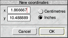
Enter coordinate leads to a dialogue box which shows the current coordinates of the point. You can select the unit the coordinates are shown in by clicking on the Inches and Centimetres buttons. To change the coordinate, type in the new value and click OK. To leave the coordinate unchanged, click Cancel or press Escape If the point you have chosen is the start point of the path, only Enter coordinate is available.

Reverse direction causes the selected path to be reversed. In many cases this may have no visual impact on the drawing, but if for example you have a path with an arrowhead at one end only, the change will be clearly visible when you reverse the direction of the path. Reversing direction may also affect complex paths with transparent sections (depending on the current winding rule).
Snap to grid causes the selected object to align with the grid.
To leave Path edit mode, click SELECT elsewhere in the diagram.
Cancelling your last operation
Undo cancels the last operation you carried out. restoring your work to its previous state,
Redo cancels Undo, if you decide you were right after all.

|
![[Select]](../images/ro6doc.gif)
![[Select]](../images/ro6doc.gif)