
|
www.riscos.com Technical Support: |
This appendix defines three file formats used to store processed code and the format of debugging data used by debuggers:
Language processors such as CC and ObjAsm generate processed code output as AOF files. An ALF file is a collection of AOF files constructed from a set of AOF files by the LibFile tool. The Link tool accepts a set of AOF and ALF files as input, and by default produces an executable program file as output in AIF.
Throughout this appendix the terms byte, half word, word, and string are used to mean the following:
Byte: 8 bits, considered unsigned unless otherwise stated, usually used to store flag bits or characters.
Half word:16 bits, or 2 bytes, usually unsigned. The least significant byte has the lowest address (DEC/Intel byte sex, sometimes called little endian). The address of a half word (ie of its least significant byte) must be divisible by 2.
Word: 32 bits, or 4 bytes, usually used to store a non-negative value. The least significant byte has the lowest address (DEC/Intel byte sex, sometimes called little endian). The address of a word (ie of its least significant byte) must be divisible by 4.
String: A sequence of bytes terminated by a NUL (0X00) byte. The NUL is part of the string but is not counted in the string's length. Strings may be aligned on any byte boundary.
For emphasis: a word consists of 32 bits, 4-byte aligned; within a word, the least significant byte has the lowest address. This is DEC/Intel, or little endian, byte sex, not IBM/Motorola byte sex.
Fields not explicitly defined by this appendix are implicitly reserved to Acorn. It is required that all such fields be zeroed. Acorn may ascribe meaning to such fields at any time, but will usually do so in a manner which gives no new meaning to zeroes.
An object or library file contains a number of separate but related pieces of data. In order to simplify access to these data, and to provide for a degree of extensibility, the object and library file formats are themselves layered on another format called Chunk File Format, which provides a simple and efficient means of accessing and updating distinct chunks of data within a single file. The object file format defines five chunks:
The library file format defines four chunks:
There may be many data chunks in a library.
The minimum size of a piece of data in both formats is four bytes or one word. Each word is stored in a file in little-endian format; that is the least significant byte of the word is stored first.
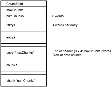
A chunk is accessed via a header at the start of the file. The header contains the number, size, location and identity of each chunk in the file. The size of the header may vary between different chunk files but is fixed for each file. Not all entries in a header need be used, thus limited expansion of the number of chunks is permitted without a wholesale copy. A chunk file can be copied without knowledge of the contents of the individual chunks.
Graphically, the layout of a chunk file is as follows:

ChunkFileId marks the file as a chunk file. Its value is C3CBC6C5 hex. The maxChunks field defines the number of the entries in the header, fixed when the file is created. The numChunks field defines how many chunks are currently used in the file, which can vary from 0 to maxChunks. The value of numChunks is redundant as it can be found by scanning the entries.
Each entry in the header comprises four words in the following order:
The chunkId field provides a conventional way of identifying what type of data a chunk contains. It is split into two parts. The first four characters (in the first word) contain a universally unique name allocated by a central authority (Acorn). The remaining four characters (in the second word) can be used to identify component chunks within this universal domain. In each part, the first character of the name is stored first in the file, and so on.
For AOF files, the first part of each chunk's name is OBJ_; the second components are defined later. For ALF files, the first part is LIB_.
Each piece of an object file is stored in a separate, identifiable, chunk. AOF defines five chunks as follows:
| Chunk | Chunk Name |
|---|---|
| Header | OBJ_HEAD |
| Areas | OBJ_AREA |
| Identification | OBJ_IDFN |
| Symbol Table | OBJ_SYMT |
| String Table | OBJ_STRT |
Only the header and areas chunks must be present, but a typical object file will contain all five of the above chunks.
A feature of chunk file format is that chunks may appear in any order in the file. However, language processors which must also generate other object formats - such as UNIX's a.out format - should use this flexibility cautiously.
A language translator or other system utility may add additional chunks to an object file, for example a language-specific symbol table or language-specific debugging data, so it is conventional to allow space in the chunk header for additional chunks; space for eight chunks is conventional when the AOF file is produced by a language processor which generates all five chunks described here.
The header chunk should not be confused with the chunk file's header.
The AOF header is logically in two parts, though these appear contiguously in the header chunk. The first part is of fixed size and describes the contents and nature of the object file. The second part is variable in length (specified in the fixed part) and is a sequence of area declarations defining the code and data areas within the OBJ_AREA chunk.
The AOF header chunk has the following format:
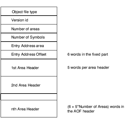
C5E2D080 (hex) marks an object file as being in relocatable object format
This word encodes the version of AOF to which the object file complies: AOF 1.xx is denoted by 150 decimal; AOF 2.xx by 200 decimal.
The code and data of the object file is presented as a number of separate areas, in the OBJ_AREA chunk, each with a name and some attributes (see below). Each area is declared in the (variable-length) part of the header which immediately follows the fixed part. The value of the Number of Areas field defines the number of areas in the file and consequently the number of area declarations which follow the fixed part of the header.
If the object file contains a symbol table chunk OBJ_SYMT, then this field defines the number of symbols in the symbol table.
One of the areas in an object file may be designated as containing the start address for any program which is linked to include this file. If so, the entry address is specified as an <area-index, offset> pair, where area-index is in the range 1 to Number of Areas, specifying the nth area declared in the area declarations part of the header. The entry address is defined to be the base address of this area plus offset.
A value of 0 for area-index signifies that no program entry address is defined by this AOF file.
The area headers follow the fixed part of the AOF header. Each area header has the following form:
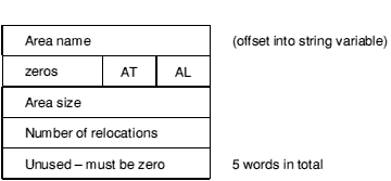
Each name in an object file is encoded as an offset into the string table, which stored in the OBJ_STRT chunk. This allows the variable-length characteristics of names to be factored out from primary data formats. Each area within an object file must be given a name which is unique amongst all the areas in that object file.
This byte must be set to 2; all other values are reserved to Acorn.
Each area has a set of attributes encoded in the AT byte. The least-significant bit of AT is numbered 0.
Link orders areas in a generated image first by attributes, then by the (case-significant) lexicographic order of area names, then by position of the containing object module in the link-list. The position in the link-list of an object module loaded from a library is not predictable.
When ordered by attributes, Read-Only areas precede Read-Write areas which precede Debug areas; within Read-Only and Read-Write Areas, Code precedes Data which precedes Zero-Initialised data. Zero-Initialised data may not have the Read-Only attribute.
This bit must be set to 0.
If this bit is set, the area contains code, otherwise it contains data.
Bit 2 specifies that the area is a common block definition.
Bit 3 defines the area to be a (reference to a) common block and precludes the area having initialising data (see Bit 4, below). In effect, the setting of Bit 3 implies the setting of Bit 4.
Common areas with the same name are overlaid on each other by Link. The Size field of a common definition defines the size of a common block. All other references to this common block must specify a size which is smaller or equal to the definition size. In a link step there may be at most one area of the given name with bit 2 set. If none of these have bit 2 set, the actual size of the common area will be size of the largest common block reference (see also Linker defined symbols).
This bit specifies that the area has no initialising data in this object file and that the area contents are missing from the OBJ_AREA chunk. This bit is typically used to denote large uninitialised data areas. When an uninitialised area is included in an image, Link either includes a read-write area of binary zeroes of appropriate size or maps a read-write area of appropriate size that will be zeroed at image start-up time. This attribute is incompatible with the read-only attribute (see the section on Bit 5, below).
Note: Whether or not a zero-initialised area is re-zeroed if the image is re-entered is a property of Link and the relevant image format. The definition of AOF neither requires nor precludes re-zeroing.
This bit specifies that the area is read-only. Link groups read-only areas together so that they may be write protected at run-time, hardware permitting. Code areas and debugging tables should have this bit set. The setting of this bit is incompatible with the setting of bit 4.
This bit must be set to 0.
This bit specifies that the area contains symbolic debugging tables. Link groups these areas together so they can be accessed as a single contiguous chunk at run-time. It is usual for debugging tables to be read-only and, therefore, to have bit 5 set too. If bit 7 is set, bit 1 is ignored.
This field specifies the size of the area in bytes, which must be a multiple of 4. Unless the Not Initialised bit (bit 4) is set in the area attributes, there must be this number of bytes for this area in the OBJ_AREA chunk.
This specifies the number of relocation directives which apply to this area.
The areas chunk (OBJ_AREA) contains the actual areas (code, data, zero- initialised data, debugging data, etc.) plus any associated relocation information. Its chunkId is OBJ_AREA. Both an area's contents and its relocation data must be word-aligned. Graphically, the layout of the areas chunk is:
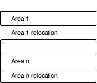
An area is simply a sequence of byte values, the order following that of the addressing rules of the ARM, that is the least significant byte of a word is first. An area is followed by its associated relocation table (if any). An area is either completely initialised by the values from the file or not initialised at all (ie it is initialised to zero in any loaded program image, as specified by bit 4 of the area attributes).
If no relocation is specified, the value of a byte/half word/word in the preceding area is exactly the value that will appear in the final image.
Bytes and half words may only be relocated by constant values of suitably small size. They may not be relocated by an area's base address.
A field may be subject to more than one relocation.
There are 2 types of relocation directive, termed here type-1 and type-2. Type-2 relocation directives occur only in AOF versions 1.50 and later.
Relocation can take two basic forms: Additive and PCRelative.
Additive relocation specifies the modification of a byte/half word/word, typically containing a data value (ie constant or address).
PCRelative relocation always specifies the modification of a branch (or branch with link) instruction and involves the generation of a program- counter-relative, signed, 24-bit word-displacement.
Additive relocation directives and type-2 PC-relative relocation directives have two variants: Internal and Symbol.
Additive internal relocation involves adding the allocated base address of an area to the field to be relocated. With Type-1 internal relocation directives, the value by which a location is relocated is always the base of the area with which the relocation directive is associated (the Symbol IDentification field (SID) is ignored). In a type-2 relocation directive, the SID field specifies the index of the area relative to which relocation is to be performed. These relocation directives are analogous to the TEXT-, DATA- and BSS-relative relocation directives found in the a.out object format.
Symbol relocation involves adding the value of the symbol quoted.
A type-1 PCRelative relocation directive always references a symbol. The relocation offset added to any pre-existing in the instruction is the offset of the target symbol from the PC current at the instruction making the PCRelative reference. Link takes into account the fact that the PC is eight bytes beyond that instruction.
In a type-2 PC-relative relocation directive (only in AOF version 1.50 and later) the offset bits of the instruction are initialised to the offset from the base of the area of the PC value current at the instruction making the reference - thus the language translator, not Link, compensates for the difference between the address of the instruction and the PC value current at it. This variant is introduced in direct support of compilers that must also generate UNIX's a.out format.
For a type-2 PC-relative symbol-type relocation directive, the offset added into the instruction making the PC-relative reference is the offset of the target symbol from the base of the area containing the instruction. For a type-2, PC-relative, internal relocation directive, the offset added into the instruction is the offset of the base of the area identified by the SID field from the base of the area containing the instruction.
Link itself may generate type-2, PC-relative, internal relocation directives during the process of partially linking a set of object modules.
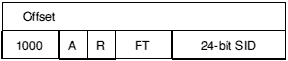
Diagrammatically:
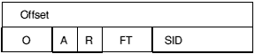
Offset is the byte offset in the preceding area of the field to be relocated.
If a symbol is involved in the relocation, this 16-bit field specifies the index within the symbol table (see below) of the symbol in question.
This 2-bit field (bits 16 - 17) specifies the size of the field to be relocated:
| 00 | byte |
| 01 | half word |
| 10 | word |
| 11 | illegal value |
This field (bit 18) has the following interpretation:
| 0 | Additive relocation |
| 1 | PC-Relative relocation |
In a type-1 relocation directive, this 1-bit field (bit 19) is only interpreted if bit 18 is a zero.
A=0 specifies Internal relocation, meaning that the base address of the area (with which this relocation directive is associated) is added into the field to be relocated. A=1 specifies Symbol relocation, meaning that the value of the given symbol is added to the field being relocated.
Bits 20-31 are reserved by Acorn and should be written as zeroes.
These are available from AOF 1.50 onwards.
The interpretation of Offset, FT and SID is exactly the same as for type-1 relocation directives except that SID is increased from 16 to 24 bits and has a different meaning - described below - if A=0).
The second word of a type-2 relocation directive contains 1 in its most significant bit; bits 28 - 30 must be written as 0, as shown.
The different interpretation of the R bit in type-2 directives has already been described in Relocation directives.
If A=0 (internal relocation type) then SID is the index of the area, in the OBJ_AREA chunk, relative to which the value at Offset in the current area is to be relocated. Areas are indexed from 0.
The Number of Symbols field in the header defines how many entries there are in the symbol table. Each symbol table entry has the following format:
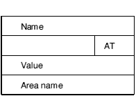
This value is an index into the string table (in chunk OBJ_STRT) and thus locates the character string representing the symbol.
This is a 7 bit field specifying the attributes of a symbol as follows:
(10 means bit 1 set, bit 0 unset).
| 01 | The symbol is defined in this object file and has scope limited to this object file (when resolving symbol references, Link will only match this symbol to references from other areas within the same object file). |
|---|---|
| 10 | The symbol is a reference to a symbol defined in another area or another object file. If no defining instance of the symbol is found then Link attempts to match the name of the symbol to the names of common blocks. If a match is found it is as if there were defined an identically-named symbol of global scope, having as value the base address of the common area. |
| 11 | The symbol is defined in this object file and has global scope (ie when attempting to resolve unresolved references, Link will match this symbol to references from other object files). |
| 00 | Reserved by Acorn. |
This attribute is only meaningful if the symbol is a defining occurrence (bit 0 set). It specifies that the symbol has an absolute value, for example, a constant. Otherwise its value is relative to the base address of the area defined by the Area Name field of the symbol table entry.
This bit is only meaningful if bit 0 is unset (that is, the symbol is an external reference). Bit 3 denotes that the reference is case-insensitive. When attempting to resolve such an external reference, Link will ignore character case when performing the match.
This bit is only meaningful if the symbol is an external reference (bits 1,0 = 10). It denotes that the reference is weak, that is that it is acceptable for the reference to remain unsatisfied and for any fields relocated via it to remain unrelocated.
Note: A weak reference still causes a library module satisfying that reference to be auto-loaded.
This bit is only meaningful if the symbol is a defining, external occurrence (ie if bits 1,0 = 11). It denotes that the definition is strong and, in turn, this is only meaningful if there is a non-strong, external definition of the same symbol in another object file. In this scenario, all references to the symbol from outside of the file containing the strong definition are resolved to the strong definition. Within the file containing the strong definition, references to the symbol resolve to the non-strong definition.
This attribute allows a kind of link-time indirection to be enforced. Usually, strong definitions will be absolute and will be used to implement an operating system's entry vector which must have the forever binary property.
This bit is only meaningful if bits 1,0 = 10. Bit 6 denotes that the symbol is a common symbol - in effect, a reference to a common area with the symbol's name. The length of the common area is given by the symbol's value field (see below). Link treats common symbols much as it treats areas having the common reference bit set - all symbols with the same name are assigned the same base address and the length allocated is the maximum of all specified lengths.
If the name of a common symbol matches the name of a common area then these are merged and symbol identifies the base of the area.
All common symbols for which there is no matching common area (reference or definition) are collected into an anonymous linker pseudo-area.
This field is only meaningful if the symbol is a defining occurrence (ie bit 0 of AT set) or a common symbol (ie bit 6 of AT set). If the symbol is absolute (bit 2 of AT set), this field contains the value of the symbol. Otherwise, it is interpreted as an offset from the base address of the area defined by Area Name, which must be an area defined in this object file.
This field is only meaningful if the symbol is not absolute (ie if bit 2 of AT is unset) and the symbol is a defining occurrence (ie bit 0 of AT is set). In this case it gives the index into the string table of the character string name of the (logical) area relative to which the symbol is defined.
The string table chunk contains all the print names referred to within the areas and symbol table chunks. The separation is made to factor out the variable length characteristic of print names. A print name is stored in the string table as a sequence of ISO8859 non-control characters terminated by a NUL (0) byte and is identified by an offset from the table's beginning. The first 4 bytes of the string table contain its length (including the length word - so no valid offset into the table is less than 4 and no table has length less than 4). The length stored at the start of the string table itself is identically the length stored in the OBJ_STRT chunk header.
This chunk should contain a printable character string (characters in the range [32 - 126]), terminated by a NUL (0) byte, giving information about the name and version of the language translator which generated the object file.
Though not part of the definition of AOF, the definitions of symbols which the AOF linker defines during the generation of an image file are collected here. These may be referenced from AOF object files, but must not be redefined.
The pre-defined symbols occur in Base/Limit pairs. A Base value gives the address of the first byte in a region and the corresponding Limit value gives the address of the first byte beyond the end of the region. All pre-defined symbols begin Image$$ and the space of all such names is reserved by Acorn.
None of these symbols may be redefined. The pre-defined symbols are:
| Image$$RO$$Base | Address and limit of the Read-Only section of the image. |
| Image$$RO$$Limit | |
| Image$$RW$$Base | Address and limit of the Read-Write section of the image. |
| Image$$RW$$Limit | |
| Image$$ZI$$Base | Address and limit of the Zero-initialised data section of the image (created from areas having bit 4 of their area attributes set and from common symbols which match no area name). |
| Image$$ZI$$Limit |
If a section is absent, the Base and Limit values are equal but unpredictable.
| Image$$RO$$Base | includes any image header prepended by Link. |
| Image$$RW$$Limit | includes (at the end of the RW section) any zero-initialised data created at run-time. |
The Image$$xx$${Base,Limit} values are intended to be used by language run-time systems. Other values which are needed by a debugger or by part of the pre-run-time code associated with a particular image format are deposited into the relevant image header by Link.
For each common area, Link defines a global symbol having the same name as the area, except where this would clash with the name of an existing global symbol definition (thus a symbol reference may match a common area).
The following subsections describe features that were part of revision 1.xx of AOF and/or that were supported by the 59x releases of the AOF linker, which are no longer supported. In each case, a brief rationale for the change is given.
AOF used to define three image types as well as a relocatable object file type. Image types 2 and 3 were never used under Arthur/RISC OS and are now obsolete. Image type 1 is used only by the obsolete Dbug (DDT has Dbug's functionality and uses Application Image Format).
| AOF Image type 1 | C5E2D081 hex (obsolescent) |
| AOF Image type 2 | C5E2D083 hex (obsolete) |
| AOF Image type 3 | C5E2D087 hex (obsolete) |
AOF used to allow the alignment of an area to be any specified power of 2 between 2 and 16. By convention, relocatable object code areas always used minimal alignment (AL=2) and only the obsolete image formats, types 2 and 3, specified values other than 2. From now on, all values other than 2 are reserved by Acorn.
Two attributes have been withdrawn: the Absolute attribute (bit 0 of AT) and the Position Independent attribute (bit 6 of AT).
The Absolute attribute was not supported by the RISC OS linker and therefore had no utility. Link in any case allows the effect of the Absolute attribute to be simulated.
The Position Independent bit used to specify that a code area was position independent, meaning that its base address could change at run-time without any change being required to its contents. Such an area could only contain internal, PC-relative relocations and must make all external references through registers. Thus only code and pure data (containing no address values) could be position-independent.
Few language processors generated the PI bit which was only significant to the generation of the obsolete image types 2 and 3 (in which it affected AREA placement). Accordingly, its definition has been withdrawn.
The concept of fragmented areas was introduced in release 0.04 of AOF, tentatively in support of Fortran compilers. To the best of our knowledge, fragmented areas were never used. (Two warnings against use were given with the original definition on the grounds of: structural incompatibility with UNIX's a.out format; and likely inefficient handling by Link. And use was hedged around with curious restrictions). Accordingly, the definition of fragmented areas is withdrawn.
There are two library file formats described here, termed new-style and old-style. Link can read both formats, though no tool will actually generate an old-style library.
Currently, only the Acorn/Topexpress Fortran-77 compiler generates old-style libraries (which it does instead of generating AOF object files). Link handles these libraries specially, including every member in the output image unless explicitly instructed otherwise.
Old-style libraries are obsolescent and should no longer be generated.
Each piece of a library file is stored in a separate, identifiable, chunk, named as follows:
| Chunk | Chunk Name | |
|---|---|---|
| Directory | LIB_DIRY | |
| Time-stamp | LIB_TIME | |
| Version | LIB_VSRN | - new-style libraries only |
| Data | LIB_DATA | |
| Symbol table | OFL_SYMT | - object code libraries only |
| Time-stamp | OFL_TIME | - object code libraries only |
There may be many LIB_DATA chunks in a library, one for each library member.
The LIB_DIRY chunk contains a directory of all modules in the library each of which is stored in a LIB_DATA chunk. The directory size is fixed when the library is created. The directory consists of a sequence of variable length entries, each an integral number of words long. The number of directory entries is determined by the size of the LIB_DIRY chunk.
This is shown pictorially in the following diagram:
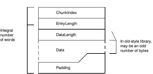
The ChunkIndex is a 0 origin index within the chunk file header of the corresponding LIB_DATA chunk. The LIB_DATA chunk entry gives the offset and size of the library module in the library file. A ChunkIndex of 0 means the directory entry is not in use.
The number of bytes in this LIB_DIRY entry, always a multiple of 4.
The number of bytes used in the Data section of this LIB_DIRY entry. This need not be a multiple of 4, though it always is in new-style libraries.
The data section consists of a 0 terminated string followed by any other information relevant to the library module. Strings should contain only ISO-8859 non-control characters (ie codes [0-31], 127 and 128+[0-31] are excluded). The string is the name used by the library management tools to identify this library module. Typically this is the name of the file from which the library member was created.
In new-style libraries, an 8-byte, word-aligned time-stamp follows the member name. The format of this time-stamp is described in the LIB_TIME. Its value is (an encoded version of) the time-stamp (ie the last modified time) of the file from which the library member was created.
Applications which create libraries or library members should ensure that the LIB_DIRY entries they create contain valid time-stamps. Applications which read LIB_DIRY entries should not rely on any data beyond the end of the name-string being present unless the difference between the DataLength field and the name-string length allows for it. Even then, the contents of a time-stamp should be treated cautiously and not assumed to be sensible.
Applications which write LIB_DIRY or OFL_SYMT entries should ensure that padding is done with NUL (0) bytes; applications which read LIB_DIRY or OFL_SYMT entries should make no assumptions about the values of padding bytes beyond the first, string-terminating NUL byte.
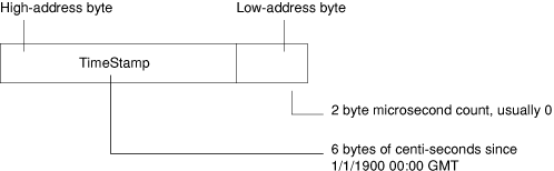
The LIB_TIME chunk contains a 64 bit time-stamp recording when the library was last modified, in the following format:
In new-style libraries, this chunk contains a 4-byte version number. The current version number is 1. Old-style libraries do not contain this chunk.
A LIB_DATA chunk contains one of the library members indexed by the LIB_DIRY chunk. No interpretation is placed on the contents of a member by the library management tools. A member could itself be a file in chunk file format or even another library.
An object code library is a library file whose members are files in AOF. All libraries you are likely to use with the DDE are object code libraries.
Additional information is stored in two extra chunks, OFL_SYMT and OFL_TIME.
OFL_SYMT contains an entry for each external symbol defined by members of the library, together with the index of the chunk containing the member defining that symbol.
The OFL_SYMT chunk has exactly the same format as the LIB_DIRY chunk except that the Data section of each entry contains only a string, the name of an external symbol (and between 1 and 4 bytes of NUL padding). OFL_SYMT entries do not contain time-stamps.
The OFL_TIME chunk records when the OFL_SYMT chunk was last modified and has the same format as the LIB_TIME chunk (see above).
AIF is the format of executable program files produced by linking AOF files. Example AIF files are !RunImage files of applications coded in C or assembler.
Debugging tables have the property that all references from them to code and data (if any) are in the form of relocatable addresses. After loading an image at its load address these values are effectively absolute. All references between debugger table entries are in the form of offsets from the beginning of the debugging data area. Thus, following relocation of a whole image, the debugging data area itself is position independent and can be copied by the debugger.
The layout of an AIF image is as follows:
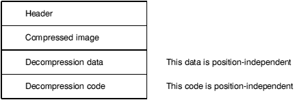
The header is small, fixed in size, and described below. In a compressed AIF image, the header is NOT compressed.
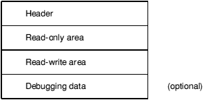
Once an image has been decompressed - or if it is uncompressed in the first place - it has the following layout:
Debugging data are absent unless the image has been linked appropriately and, in the case of source-level debugging, unless the constituent components of the image have been compiled appropriately.
The relocation list is a list of byte offsets from the beginning of the AIF header, of words to be relocated, followed by a word containing -1. The relocation of non-word values is not supported.
After the execution of the self-relocation code - or if the image is not self-relocating - the image has the following layout:
At this stage a debugger is expected to copy the debugging data (if present) somewhere safe, otherwise they will be overwritten by the zero-initialised data and/or the heap/stack data of the program. A debugger can seize control at the appropriate moment by copying, then modifying, the third word of the AIF header (see below).
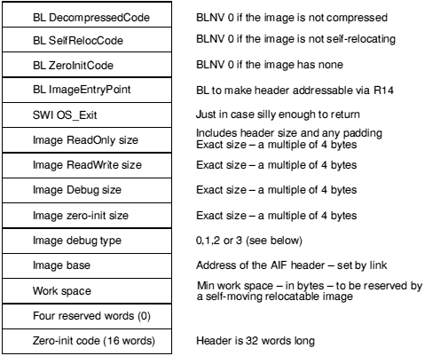
BL is used everywhere to make the header addressable via R14 (but beware the PSR bits) in a position-independent manner and to ensure that the header will be position-independent.
It is required that an image be re-enterable at its first instruction. Therefore, after decompression, the decompression code must reset the first word of the header to BLNV 0. Similarly, following self-relocation, the second word of the header must be reset to BLNV 0. This causes no additional problems with the read-only nature of the code segment - both decompression and relocation code must write to it anyway. So, on systems with memory protection, both the decompression code and the self-relocation code must be bracketed by system calls to change the access status of the read-only section (first to writable, then back to read-only).
The image debug type has the following meaning:
| 0: | No debugging data are present. |
| 1: | Low-level debugging data are present. |
| 2: | Source level (ASD) debugging data are present. |
| 3: | 1 and 2 are present together. |
All other values are reserved by Acorn.
The Zero-initialisation code is as follows:
        BIC     r11, lr, #&FC000003   ; clear status bits -> header + &C
        ADD     r11, r11, #8          ; -> Image ReadOnly size
        LDMIA   r11, {r0, r1, r2, r3} ; various sizes
        CMPS    r3, #0
        MOVLES  pc, lr                ; nothing to do
        SUB     r11, r11, #&14        ; image base
        ADD     r11, r11, r0          ; + RO size
        ADD     r11, r11, r1          ; + RW size = base of 0-init area
        MOV     r0, #0
        MOV     r1, #0
        MOV     r2, #0
        MOV     r4, #0
ZeroLoop
        STMIA   r11!, {r0, r1, r2, r4}
        SUBS    r3, r3, #16
        BGT     ZeroLoop
        MOVS    pc, lr                ; 16 words in total.
AIFHeader.ImageBase = Image$$RO$$Base
AIFHeader.ImageBase + AIFHeader.ROSize = Image$$RW$$Base
AIFHeader.ImageBase + AIFHeader.ROSize + AIFHeader.RWSize = Image$$ZI$$Base
AIFHeader.ImageBase + AIFHeader.ROSize + AIFHeader.RWSize + AIFHeader.ZeroInitSize = Image$$RW$$Limit
Two kinds of self-relocation are supported by AIF and one by AMF; for completeness, all three are described here.
One-time position independence is supported by relocatable AIF images. Many-time position independence is required for AMF Relocatable Modules. And only AIF images can self-move to a location which leaves a requested amount of workspace.
Why are there three different kinds of self-relocation?
In this case there is no AIF header, the code must be executable many times, and it must be symbolically addressable from the Relocatable Module header. The code below must be the last area of the RMF image, following the relocation list. Note that it is best thought of as an additional area.
When the following code is executed, the module image has already been loaded at/moved to its target address. It only remains to relocate location-dependent addresses. The list of offsets to be relocated, terminated by (-1), immediately follows End. Note that the address values here (eg |__RelocCode|) will appear in the list of places to be relocated, allowing the code to be re-executed.
        IMPORT  |Image$$RO$$Base| ; where the image is linked at...
        EXPORT  |__RelocCode|     ; referenced from the RM header
|__RelocCode|
        LDR     r1, RelocCode     ; value of __RelocCode (before relocation)
        SUB     r11, pc, #12      ; value of __RelocCode now
        SUBS    r1, r11, r1       ; relocation offset
        MOVEQS  pc, lr            ; relocate by 0 so nothing to do
        LDR     r11, ImageBase    ; image base prior to relocation...
        ADD     r11, r11, r1      ; ...where the image really is
        ADR     r2, End
RelocLoop
        LDR     r0, [r2], #4
        CMNS    r0, #1            ; got list terminator?
        MOVLES  pc, lr            ; yes => return
        LDR     r3, [r11, r0]     ; word to relocate
        ADD     r3, r3, r1        ; relocate it
        STR     r3, [r11, r0]     ; store it back
        B       RelocLoop         ; and do the next one
RelocCode
        DCD     |__RelocCode|
ImageBase
        DCD     |Image$$RO$$Base|
End                               ; the list of locations to relocate
                                  ; starts here (each is an offset from the
                                  ; base of the module) and is terminated
                                  ; by -1.
Note that this code, and the associated list of locations to relocate, is added automatically to a relocatable module image by Link (as a consequence of using Link with the SetUp option Module enabled).
This code is added to the end of an AIF image by Link, immediately before the list of relocations (terminated by -1). Note that the code is entered via a BL from the second word of the AIF header so, on entry, R14 points to AIFHeader + 8.
RelocCode ROUT
        BIC     r11, lr, #&FC000003 ; clear flag bits; -> AIF header + &08
        SUB     r11, r11, #8        ; -> header address
        MOV     r0, #&FB000000      ; BLNV #0
        STR     r0, [r11, #4]       ; won't be called again on image re-entry
;does the code need to be moved?
        LDR     r9, [r11, #&2C]     ; min free space requirement
        CMPS    r9, #0              ; 0 => no move, just relocate
        BEQ     RelocateOnly
;calculate the amount to move by...
        LDR     r0, [r11, #&20]     ; image zero-init size
        ADD     r9, r9, r0          ; space to leave = min free + zero init
        SWI     GetEnv              ; MemLimit -> R1
        ADR     r2, End             ; -> End
01      LDR     r0, [r2], #4        ; load relocation offset, increment R2
        CMNS    r0, #1              ; terminator?
        BNE     %B01                ; No, so loop again
        SUB     r3, r1, r9          ; MemLimit - freeSpace
        SUBS    r0, r3, r2          ; amount to move by
        BLE     RelocateOnly        ; not enough space to move...
        BIC     r0, r0, #15         ; a multiple of 16...
        ADD     r3, r2, r0          ; End + shift
        ADR     r8, %F01            ; intermediate limit for copy-up
;
; copy everything up memory, in descending address order, branching
; to the copied copy loop as soon as it has been copied.
;
02      LDMDB   r2!, {r4-r7}
        STMDB   r3!, {r4-r7}
        CMP     r2, r8              ; copied the copy loop?
        BGT     %B02                ; not yet
        ADD     r4, pc, r0
        MOV     pc, r4              ; jump to copied copy code
03      LDMDB   r2!, {r4-r7}
        STMDB   r3!, {r4-r7}
        CMP     r2, r11             ; copied everything?
        BGT     %B03                ; not yet
        ADD     r11, r11, r0        ; load address of code
        ADD     lr, lr, r0          ; relocated return address
RelocateOnly
        LDR     r1, [r11, #&28]     ; header + &28 = code base set by Link
        SUBS    r1, r11, r1         ; relocation offset
        MOVEQ   pc, lr              ; relocate by 0 so nothing to do
        STR     r11, [r11, #&28]    ; new image base = actual load address
        ADR     r2, End             ; start of reloc list
RelocLoop
        LDR     r0, [r2], #4        ; offset of word to relocate
        CMNS    R0, #1              ; terminator?
        MOVEQS  pc, lr              ; yes => return
        LDR     r3, [r11, r0]       ; word to relocate
        ADD     r3, r3, r1          ; relocate it
        STR     r3, [r11, r0]       ; store it back
        B       RelocLoop           ; and do the next one
        End                         ; The list of offsets of locations to relocate
                                    ; starts here; terminated by -1.
Acknowledgement: This design is based on work originally done for Acorn Computers by Topexpress Ltd.
This section describes the format of symbolic debugging data generated by ARM compilers and assemblers running under RISC OS and used by the desktop debugger DDT.
For each separate compilation unit (called a section) the compiler produces debugging data in a special AREA of the object code (see the chapter entitled AOF for an explanation of AREAs and their attributes). Debugging data are position independent, containing only relative references to other debugging data within the same section and relocatable references to other compiler-generated AREAs.
Debugging data AREAs are combined by the linker into a single contiguous section of a program image (see the chapter entitled AIF for a description of Application Image Format). Because the debugging section is position-independent, the debugger can move it to a safe location before the image starts executing. If the image is not executed under debugger control the debugging data is simply overwritten.
The format of debugging data allows for a variable amount of detail. This potentially allows the user to trade off among memory used, disc space used, execution time, and debugging detail.
Assembly-language level debugging is also supported, though in this case the debugging tables are generated by the linker, not by language processors. These low-level debugging tables appear in an extra section item, as if generated by an independent compilation. Low-level and high-level debugging are orthogonal facilities, though DDT allows the user to move smoothly between levels if both sets of debugging data are present in an image.
A debug data AREA consists of a series of items. The arrangement of these items mimics the structure of the high-level language program itself.
For each debug AREA, the first item is a section item, giving global information about the compilation, including a code identifying the language and flags indicating the amount of detail included in the debugging tables.
Each data, function, procedure, etc., definition in the source program has a corresponding debug data item and these items appear in an order corresponding to the order of definitions in the source. This means that any nested structure in the source program is preserved in the debugging data and the debugger can use this structure to make deductions about the scope of various source-level objects. Of course, for procedure definitions, two debug items are needed: a procedure item to mark the definition itself and an endproc item to mark the end of the procedure's body and the end of any nested definitions. If procedure definitions are nested then the procedure - endproc brackets are also nested. Variable and type definitions made at the outermost level, of course, appear outside of all procedure/endproc items.
Information about the relationship between the executable code and source files is collected together and appears as a fileinfo item, which is always the final item in a debugging AREA. Because of the C language's #include facility, the executable code produced from an outer-level source file may be separated into disjoint pieces interspersed with that produced from the included files. Therefore, source files are considered to be collections of 'fragments', each corresponding to a contiguous area of executable code and the fileinfo item is a list with an entry for each file, each in turn containing a list with an entry for each fragment. The fileinfo field in the section item addresses the fileinfo item itself. In each procedure item there is a 'file entry' field which refers to the file-list entry for the source file containing the procedure's start; there is a separate one in the endproc item because it may possibly not be in the same source file.
Several of the debugging data items (eg procedure and variable) have a type word field to identify their data type. This field contains, in the most significant 3 bytes, a code to identify a base type and, in the least significant byte, a pointer count: 0 to denote the type itself; 1 to denote a pointer to the type; 2 to denote a pointer to a pointer to...; etc.
For simple types the code is a positive integer as follows:
| void | 0 | (all codes are decimal) | |
| signed integers | |||
| single byte | 10 | ||
| half-word | 11 | ||
| word | 12 | ||
| unsigned integers | |||
| single byte | 20 | ||
| half-word | 21 | ||
| word | 22 | ||
| floating point | |||
| float | 30 | ||
| double | 31 | ||
| long double | 32 | ||
| complex | |||
| single complex | 41 | ||
| double complex | 42 | ||
| functions | |||
| functions | 100 |
For compound types (arrays, structures, etc.) there is a special kind of debug data item (array, struct, etc.) to give details of the type such as array bounds and field types. The type code for such types is negative being the negation of the (byte) offset of the special item from the start of the debugging AREA.
If a type has been given a name in a source program, it will give rise to a type debugging data item which contains the name and a type word as defined above. If necessary, there will also be a debugging data item such as an array or struct to define the type itself. In that case, the type word will refer to this item.
Enumerated types in C and scalars in Pascal are treated simply as integer sub-ranges of an appropriate size, the name information is not available in the this version of the debugging format. Set types in Pascal are not treated in detail: the only information recorded for them is the total size occupied by the object in bytes.
Fortran character types are supported by a special kind of debugging data item the format of which is yet to be defined.
Several of the debugging data items have a sourcepos field to identify a position in the source file. This field contains a line number and character position within the line packed into a single word. The most significant 10 bits encode the character offset (0-based) from the start of the line and the least- significant 22 bits give the line number.
The first word of each debugging data item contains the byte length of the item (encoded in the most significant 16 bits) and a code identifying the kind of item (in the least significant 16 bits). The following codes are defined:
| 1 | section |
| 2 | procedure |
| 3 | endproc |
| 4 | variable |
| 5 | type |
| 6 | struct |
| 7 | array |
| 8 | subrange |
| 9 | set |
| 10 | fileinfo |
The meaning of the second and subsequent words of each item is defined below.
Where items include a string field, the string is packed into successive bytes beginning with a length byte, and padded at the end to a word boundary (the padding value is immaterial, but NUL or ' ' is preferred). The length of a string is in the range [0 - 255] bytes.
Where an item contains a field giving an offset in the debugging data area (usually to address another item), this means a byte offset from the start of the debugging data for the whole section (in other words, from the start of the section item).
A section item is the first item of each section of the debugging data. The first five fields are held in a single word:
| language | one byte code identifying the source language |
| debuglines | 1 bit: set  tables contain line numbers tables contain line numbers
|
| debugvars | 1 bit: set tables contain data about local variables
|
| spare | 14 reserved bits (must be zero) |
| debugversion | one byte version number of the debugging data |
| codeaddr | pointer to start of executable code in this section |
| dataaddr | pointer to start of static data for this section |
| codesize | byte size of executable code in this section |
| datasize | byte size of the static data in this section |
| fileinfo | offset in the debugging data of the file information for this section (or 0 if no fileinfo is present) |
| debugsize | total byte length of debugging data for this section |
| name or nsyms | string or integer |
The name field contains the program name for Pascal and Fortran programs. For C programs it contains a name derived by the compiler from the main file name (notionally a module name). Its syntax is similar to that for a variable name in the source language. For a low-level debugging section (language = 0) the field is treated as a 4 byte integer giving the number of symbols following.
The following language byte codes are defined:
| 0 | Low-level debugging data (notionally, assembler) |
| 1 | C |
| 2 | Pascal |
| 3 | Fortran77 |
| other | reserved to Acorn. |
The fileinfo field is 0 if no source file information is present.
The debugversion field was defined to be 1; the new debugversion for the extended debugging data format (encompassing low-level debugging data) is 2. For low-level debugging data, other fields have the following values:
| language | 0 |
| codeaddr | Image$$RO$$Base |
| dataaddr | Image$$RW$$Base |
| codesize | Image$$RO$$Limit - Image$$RO$$Base |
| datasize | Image$$RW$$Limit - Image$$RW$$Base |
| fileinfo | 0 |
| nsyms | number of symbols within the following debugging data |
| debugsize | total size of the low-level debugging data including the size of the section item |
The section item is immediately followed by nsyms symbols, each having the following format:
| stridx:24 | byte offset in string table of symbol name |
| flags:8 | (see below) |
| value | the value of the symbol |
The flags field has the following values:
| 0/1 | the symbol is a local/global symbol |
| + | (there may be many local symbols with the same name) |
| 0/2/4/6 | symbol names an absolute/code/data/zero-init value |
Note that the linker reduces all symbol values to absolute values. The flags field records the history, or origin, of the symbol in the image.
The string table is in standard AOF format. It consists of a length word followed by the strings themselves, each terminated by a NUL (0). The length word includes the length of the length word, so no offset into the string table is less than 4. The end of the string table is padded to the next word boundary.
A procedure item appears once for each procedure or function definition in the source program. Any definitions with the procedure have their related debugging data items between the procedure item and the matching endproc item. The format of procedure items is as follows:
| type | the return type if this is a function, else 0 |
| args | the number of arguments |
| sourcepos | a word encoding the source position of the start of the procedure |
| startaddr | pointer to the first instruction of the procedure |
| bodyaddr | pointer to the first instruction of the procedure body (see below) |
| endproc | offset of the related endproc item |
| fileentry | offset of the file list entry for the source file |
| name | string |
The bodyaddr field points to the first instruction after the procedure entry sequence, that is the first address at which a high-level breakpoint could sensibly be set. The startaddr field points to the beginning of the entry sequence, that is the address at which control actually arrives when the procedure is called.
A label in a source program is represented by a special procedure item with no matching endproc (the endproc field is 0 to denote this). Pascal and Fortran numerical labels are converted by the compiler into strings prefixed by '$n'.
For Fortran77, multiple entry points to the same procedure each give rise to a separate procedure item but they all have the same endproc offset referring to a single endproc item.
This item marks the end of the debugging data items belonging to a particular procedure. It also contains information relating to the procedure's return. Its format is as follows:
| sourcepos | a word encoding the position in the source file of the end of the procedure |
| endaddr | a pointer to the code byte AFTER the compiled code for the procedure |
| filentry | offset of the file list entry for the procedure's end |
| nreturns | number of procedure return points (may be 0) |
| retaddrs... | pointers to the procedure-return code |
If the procedure body is an infinite loop, there will be no return point so nreturns will be 0. Otherwise the retaddrs should each point to a suitable location at which a breakpoint may be set 'at the exit of the procedure'. When execution reaches this point, the current stack frame should still be in this procedure.
This item contains debugging data relating to a source program variable or a formal argument to a procedure (the first variable items in a procedure always describe its arguments). Its format is as follows:
| type | a type word |
| sourcepos | a word encoding the source position of the variable |
| class | a word encoding the variable's storage class |
| location | see explanation below |
| name | string |
The following codes define the storage classes of variables:
| 1 | external variables (or Fortran common) |
| 2 | static variables private to one section |
| 3 | automatic variables |
| 4 | register variables |
| 5 | Pascal var arguments |
| 6 | Fortran arguments |
| 7 | Fortran character arguments |
The meaning of the location field of a variable item depends on the storage class: it contains an absolute address for static and external variables (relocated by the linker); a stack offset (ie an offset from the frame- pointer) for automatic and var-type arguments; an offset into the argument list for Fortran arguments; and a register number for register variables (the 8 floating point registers are numbered 16 - 23).
No account is taken of variables which ought to be addressed by +ve offsets from the stack-pointer rather than -ve offsets from the frame-pointer.
The sourcepos field is used by the debugger to distinguish between different definitions having the same name (eg identically named variables in disjoint source-level naming scopes such as nested block in C).
This item is used to describe a named type in the source language (eg a typedef in C). The format is as follows:
| type | a type word (described earlier) |
| name | string |
This item is used to describe a structured data type (eg a struct in C or a record in Pascal). Its format is as follows:
| fields | the number of fields in the structure | |
| size | total byte size of the structure | |
| fieldtable... | a table of fields entries in the following format: | |
| offset | byte offset of this field within the structure | |
| type | a type word (interpretation as described earlier) | |
| name | string | |
Union types are described by struct items in which all fields have 0 offsets.
C bit fields are not treated in full detail: a bit field is simply represented by an integer starting on the appropriate word boundary (so that the word contains the whole field).
This item is used to describe a one-dimensional array. Multi-dimensional arrays are described as arrays of arrays. Which dimension comes first is dependent on the source language (different for C and Fortran). The format is as follows:
| size | total byte size of each element |
| arrayflags | (see below) |
| basetype | a type word |
| lowerbound | constant value or stack offset of variable |
| upperbound | constant value or stack offset of variable |
If the size field is zero, debugger operations affecting the whole array, rather than individual elements of it, are forbidden.
The following bit numbers in the arrayflags field are defined:
| 0 | lower bound is undefined |
| 1 | lower bound is a constant |
| 2 | upper bound is undefined |
| 3 | upper bound is a constant |
If a bound is defined and not constant then it is an integer variable on the stack and the boundvalue field contains the stack offset of the variable (from the frame-pointer).
This item is used to describe subrange typed in Pascal. It also serves to describe enumerated types in C and scalars in Pascal (in which case the base type is understood to be an unsigned integer of appropriate size). Its format is as follows:
| size | half-word: 1, 2, or 4 to indicate byte size of object |
| typecode | half-word: simple type code |
| lwb | lower bound of subrange |
| upb | upper bound of subrange |
This item is used to describe a Pascal set type. Currently, the description is only partial. The format is:
| size | byte size of the object |
This item appears once per section after all other debugging data items. The half of the header word which would usually give the item length is not required and should be set to 0.
Each source file is described by a sequence of 'fragments', each of which describes a contiguous region of the file within which the addresses of compiled code increase monotonically with source-file position. The order in which fragments appear in the sequence is not necessarily related to the source file positions to which they refer.
Note that for compilations that make no use of the #include facility, the list of fragments will have only one entry and all line-number information will be contiguous.
The item is a list of entries each with the following format:
| length | length of this entry in bytes (0 marks the final entry) | |
| date | date and time when the file was last modified | |
| filename | string (or null if the name is not known) | |
| n | number of fragments following | |
| fragments... | n fragments with the following structure... | |
| fragmentsize | length of this entry in bytes | |
| firstline | linenumber | |
| lastline | linenumber | |
| codeaddr | pointer to the start of the fragment's executab | |
| codesize | byte size of the code in the fragment | |
| lineinfo... | a variable number of line number data | |
There is one lineinfo half-word for each statement of the source file fragment which gives rise to executable code. Exactly what constitutes an executable statement may be defined by the language implementation; the definition may for instance include some declarations. The half-word can be regarded as 2 bytes: the first contains the number of bytes of code generated from the statement and cannot be zero; the second contains the number of source lines occupied by the statement (ie the difference between the line number of the start of the statement and the line number of the next statement). This may be zero if there are multiple statements on the same source line.
If the whole half-word is zero, this indicates that one of the quantities is too large to fit into a byte and that the following 2 half-words contain (in order) the number of lines followed by the number of bytes of code generated from the statement.